VOLTIXC / ENQUIRY
Request a Quote
Tell us what you need and we will review your enquiry.

By VoltixC Engineering Team · Last updated: 2026-09-28
Fast answer: To crimp wires, match the terminal and die to the wire size, strip the insulation to the barrel length, insert the conductor fully, and close the tool through its full cycle. Then check the crimp by eye and with a firm pull. A matched die and a complete tool cycle matter more than hand strength.
Close a matched die on the terminal barrel and the barrel folds down onto the strands, so copper and barrel work as one piece, electrically and mechanically. No heat goes into the joint. Solder joins wire with heat and molten filler instead, and it needs different kit and different checks. VoltixC lists the insulated ring, spade, disconnect, butt splice and ferrule families it makes by wire size on its crimp connectors page.
We wrote this page for someone at a bench with a terminal in one hand and the tool in the other. It follows the job: parts first, then how to crimp terminals in four steps, then the pull check and what to do when a crimp fails. Butt splices, ferrules, bullets and heavy lugs each have a guide of their own, linked from the routing table near the end.
Before the tool comes out, three markings should agree: the wire band printed on the terminal, the die nest marked on the tool, and a strip length taken from the terminal’s own barrel.
| Check | What to confirm | Where this guide covers it |
|---|---|---|
| Terminal wire band | VoltixC insulated ring, spade and disconnect series each list 22–16, 16–14 and 12–10 AWG bands, and some series add 14–12, 8 or 6 AWG; your wire has to sit inside the band | Matching the terminal, wire and die |
| Insulation outside diameter | According to TE Connectivity, wires of the same AWG size can differ in insulation diameter, so the insulation barrel has to fit the wire’s actual outside diameter | Matching the terminal, wire and die |
| Die nest or crimp position | The nest carries the same band as the terminal; according to ABB, its vinyl-insulated ring terminals use red for 0.5–1.5 mm², blue for 1.5–2.5 mm² and yellow for 4.0–6.0 mm² | Die profile and cross-section |
| Strip length | Equal to the length of the terminal’s wire barrel, not a fixed figure | Step 2 of the crimping steps |
| Insertion depth | The conductor reaches the end of the wire barrel and the insulation stops at the barrel edge | Step 3 of the crimping steps |
| Tool cycle | The jaws close through the full stroke; a ratchet tool opens only at the end of it | Step 3 of the crimping steps |
| Visual check | Indent centered on the wire barrel; the insulation barrel holds the insulation without cutting it | Checking a crimp |
| Pull check | A firm hand pull moves nothing; pull-force values come from the applicable standard or the terminal maker | Checking a crimp |
Source: Terminal bands: VoltixC supplier data as listed (not individually re-tested); other rows from the sources cited in each section.
Crimping electrical connectors of any family starts from these eight checks, which is why this wire crimp how-to puts them ahead of the steps. If one row fails, change the terminal or the die before any insulation comes off; hand force won’t fix a wrong part or a wrong nest. Pull-force pass values are not part of this wire crimping how-to, so take them from your standard or the terminal maker.
A crimp presses the terminal’s metal barrel onto the conductor until the two work as one electrical and mechanical joint, with no heat and no filler metal, and it is the right joint for any terminal made to be crimped.
| Problem | What to do | Check |
|---|---|---|
| An insulated terminal has two barrels to crimp | Put the hard squeeze on the wire barrel and a light one on the insulation barrel. In TE Connectivity‘s guide, the wire barrel provides the electrical and mechanical connection, while the insulation barrel provides strain relief, takes a more relaxed crimp and makes no electrical connection | The sleeve stops sliding when the wire flexes and shows no crack |
| The sleeve cracks as you crimp | Cut the terminal off and crimp a new one in the insulated-terminal nest | The new sleeve is whole; a crack means the die squeezed both zones equally hard |
| Stranded wire has to go onto a stud, a tab or a terminal block | Fit a terminal made for crimping | The band printed on the terminal covers the wire size |
| A wire run needs a repair or an extension | Join the two ends with a wire-to-wire splice | Each side holds when you pull it firmly by hand |
| The work is on site, where a soldering iron or an open flame may be impractical | Crimp with a hand tool and the matching die | The tool finishes its stroke on every joint |
| Every joint must come out the same | Use a tool with its die, which repeats a joint in a way hand skill cannot | The indent sits in the same place from one joint to the next |
| A soldering iron could scorch the wires next to the joint, as inside a finished panel | Crimp instead: a crimp puts no heat into the sleeve or the insulation around it | The insulation next to the joint is unmarked |
| Heavy cable is going into a copper tube lug | Close the lug barrel around the conductor with a hexagonal die | The die size matches the conductor cross-section |
| You are not sure whether to crimp or solder | Check the terminal design and the installation rules for your equipment | The terminal maker designed the part as a crimp terminal, with its barrel and sleeve sized for a die |
| You are new to the job and asking how do you crimp wire connectors, or how to wire crimp connectors into a harness | Work through the four steps further down: match, strip, crimp and check | Each step ends on its “Done right” sign |
| A crimped terminal has to come off (how to uncrimp wires) | Cut it off and crimp a new terminal; a crimp is a one-time joint, and prying the barrel open can nick the strands | The replacement terminal is crimped once, in the right nest |
The four steps further down answer how do you crimp a wire; this table settles whether a crimp is the right joint at all. Use crimp joints wherever the terminal was made for a die: the crimping of wires then takes a wire stripper or other stripping tool and a tool with the matching die, with no solder or flux. If the installation rules call for solder, follow them. Crimping lugs onto heavy cable is also called cable lugging, and people asking what is crimping in lugs mean the same job at a bigger size; those lugs are on the lug terminal page.
Pick the terminal wire band that contains your conductor size, check that the insulation barrel takes the wire’s real outside diameter, and set the tool to the die nest marked for the same band. When crimping wire connectors, the wire, the terminal and the tool each supply one input in the table, and each input fixes one part of the crimp.
| Input | How to get it | What it decides |
|---|---|---|
| Conductor size (AWG or mm²) | Printed on the wire jacket or given in the wire specification | The terminal wire band and the die nest |
| Insulation outside diameter | Measure it with a caliper; according to Engineering ToolBox, the real outside diameter is the conductor diameter plus the insulation thickness | Whether the insulation barrel can close on the wire |
| Stranded or solid conductor | The wire specification, or a look at the cut end | How carefully the strands must be kept together, and whether a ferrule goes on before a screw clamp |
| Terminal wire band or sleeve color | Printed on the terminal, the sleeve or the pack label | Which die nest to use; check the color against the terminal maker’s chart |
| Die nest marking | Stamped or color-marked on the tool jaw | Must agree with the terminal band before the crimp |
Measure the outside diameter even when you know the conductor size, since the size says nothing about how thick the wire insulation is. TE Connectivity’s crimping guide notes that insulation diameters vary among wires of the same AWG size, so the insulation barrel must accommodate the wire’s outside diameter and the crimp range must match it. A thick-jacketed wire can sit in the right conductor band and still be too fat for the insulation barrel.
Worked example: Take a 14 AWG stranded wire. It falls inside the 16–14 AWG band that VoltixC lists for its insulated terminals, so the die nest marked 16–14 AWG is the one to use. Measure the insulation outside diameter on its own, and if the insulation barrel cannot close on it, change to a terminal with a larger insulation barrel rather than moving up a die nest.
| Problem | What to do | Check |
|---|---|---|
| Sleeve colors differ from maker to maker | Go by the band printed on your own terminal. On ABB‘s vinyl-insulated ring terminals, red denotes 0.5–1.5 mm², blue 1.5–2.5 mm² and yellow 4.0–6.0 mm², and that is one maker’s example | The color on your terminal matches its own maker’s chart |
| The wire size is given in AWG and the terminal band in mm², or the other way round | Convert with the cable lug size chart | Both figures land in the same band |
| The wire size sits on the edge of two bands | Measure the insulation outside diameter and read the terminal maker’s chart; the VoltixC listings put 16 AWG in both the 22–16 and the 16–14 AWG bands | The band you pick grips the insulation without cutting it |
| A new batch is about to start | Crimp one sample and pull it hard by hand | The band and nest that passed are written down before the batch runs |
| The wire is 22 gauge (how to crimp 22 gauge wire) | Pick a terminal whose band starts at 22 AWG, such as the 22–16 AWG band in the VoltixC listings, and the nest marked for that band | No strand folds back as the thin conductor goes in |
Strip wires only after the wire and connector agree on band and nest, then insert the wire until the conductor reaches the barrel end. This guide leaves the AWG to mm² conversion table to the cable lug size chart. With the passing setup on record, the next batch starts from the same band and nest.
Start from the terminal family to get the die profile, then use the conductor cross-section to pick the nest inside that die; the tool class follows from the die.
| Terminal family | Typical die profile | Cross-section cue | Tool class |
|---|---|---|---|
| Insulated crimp terminals (vinyl or nylon sleeve) | Nest that crimps through the sleeve, with a separate zone for the insulation barrel | AWG band or sleeve color on the terminal | Ratcheting hand tool with insulated-terminal dies |
| Non-insulated open-barrel terminals | Nest sized for the bare barrel | AWG band stamped on the terminal or the pack | Hand tool with non-insulated dies |
| Wire ferrules | Square, trapezoid or hexagonal profile that forms the ferrule around the strands | Conductor size in mm² or AWG | Ferrule crimp tool; see the wire ferrule guide |
| Heavy copper tube lugs | Hexagonal die sized for the conductor | Conductor cross-section and lug barrel size | Mechanical or hydraulic lug crimp tool; see lug terminal |
| Butt splices | The same nest as the matching insulated or bare terminal, used once on each side | AWG band on the splice | The same tool as that terminal family |
| Problem | What to do | Check |
|---|---|---|
| Only pliers or a hammer are at hand | Get the die the terminal maker specifies; pliers and hammers are not recommended because they leave an uneven indent and cannot give a full, repeatable stroke | The tool closes through its full stroke on every crimp |
| The die in the tool is from the wrong band | Change to the nest marked with the terminal’s band, or the conductor may work loose or the barrel may split | The nest marking and the band on the terminal agree |
| A new box of parts is opened | Compare the nest marking with the band on the terminal again | The first crimp from the box uses the agreed nest |
| The wire moves up a size within one family | Step up to the next nest in the same die | The nest band covers the new wire size |
The table sorts crimpers by the die they take, since the die shapes the crimp. VoltixC does not supply crimp tools, so this section names die shapes and nests, not tool brands or models. For a family missing from the table, use the die the terminal maker specifies.
Knowing how to crimp wire terminals comes down to four steps: match, strip, crimp and check. Every step below gives one action and the sign that it worked, and a missing sign sends you back to that step before you go on.
Match the tool and die to the terminal and wire.
Done right: the wire size, the band printed on the terminal and the die nest marking all agree.
Strip the insulation to the barrel length.
Done right: the bare conductor fills the wire barrel, no insulation enters the wire barrel, and no long tail of copper sticks out past it.
Insert the conductor fully and crimp through the full tool cycle.
Done right: the conductor sits at the end of the barrel, the indent lands in the middle of the wire barrel, and a ratchet tool releases on its own.
Inspect the crimp and give it a firm pull.
Done right: the indent is in the right place, the insulation is not split, and the wire does not move when you pull by hand.
Take the strip length from the terminal itself, because no single figure fits every part. Hold the terminal beside the wire, mark the end of the wire barrel on the insulation, and strip to that mark. Give stranded wire a light twist in its existing lay so no strand folds back as the conductor goes in.
Tip: A butt splice gets one crimp per end. Do the first end, tug it, and only then feed the second wire in; both ends use the same nest.
Check the routing table near the end for the guide to your terminal family.
Look at every crimp, then pull it by hand, and cut off any joint that fails either check.
| Problem | What to do | Check |
|---|---|---|
| Indent off-center or on the barrel edge | Cut the terminal off and crimp a new one with the barrel seated in the nest | Indent centered on the wire barrel, clear of the barrel edge and the insulation barrel |
| Conductor tip short of the barrel end | Re-strip and push the conductor in until it reaches the end of the wire barrel | Conductor tip level with the end of the wire barrel or just past it |
| Sleeve cracked, cut or loose on the insulation | Crimp a new terminal in the insulated-terminal nest | The insulation barrel grips the insulation firmly and the sleeve has no crack or cut |
| Strand outside the barrel or folded back along the wire | Twist the strands lightly in their lay and crimp a fresh terminal | Every strand sits inside the wire barrel |
| Tongue or tab bent or cracked by the tool | Use a new terminal and hold it square to the jaws | Tongue or tab straight, with no bend or crack |
| The crimp passed the look and still needs the pull | Hold the terminal and pull the wire hard by hand, straight along its axis | Nothing moves |
| Pull checks run without process control | Keep the process controlled and check pull force continuously; a NASA technical report ties reliable crimped contacts to strict process controls and continuous pull-force verification | Pass values come from your standard or the terminal maker’s instructions, and this guide gives none |
Telling a good crimp vs bad crimp takes both checks, and the looking comes first because a misplaced indent or a split sleeve is visible before any force goes on the wire. To properly crimp a terminal, it has to pass every row above; one that survives the pull but fails a row still gets cut off.
Never re-crimp a failed joint: cut the terminal off, strip fresh wire and crimp a new terminal once, in the right nest, through the full tool stroke.
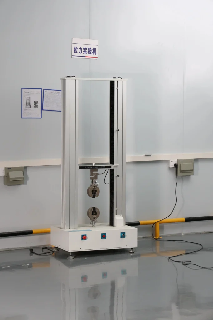
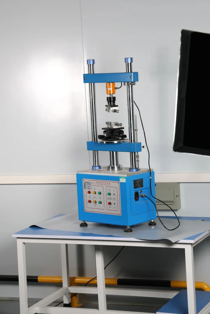
Four setup errors sit behind the failures in this table: a wire band that does not fit the wire, the wrong die nest, a conductor that stopped short of the barrel end, or an indent on the insulation instead of the metal. Match what you see to the Symptom column, and apply the fix in that row once the cause is confirmed.
| Symptom | Likely cause | Fix |
|---|---|---|
| Wire pulls out with a light tug | Terminal band too large for the wire, wrong die nest, or conductor short of the barrel end | Cut it off; re-strip; crimp a new terminal in the correct band and nest |
| Copper strands outside the barrel or splayed | Strands left untwisted, or the strip too long | Cut it off; twist the strands lightly; strip to the barrel length |
| Insulation sleeve split or cut | A non-insulated nest used on an insulated terminal, or the insulation barrel crimped as hard as the wire barrel | Use the insulated-terminal nest, which gives the insulation barrel a relaxed crimp |
| Indent on the insulation, not the metal | Strip too short, or the terminal not seated in the nest | Strip to the barrel mark; seat the barrel in the nest before closing the tool |
| Barrel cracked, bent or flattened off-center | Die nest too small, pliers or a hammer, or the barrel held crooked in the jaws | New terminal; correct nest; hold the terminal square to the jaws |
| Insulation barrel will not close, or grips loosely | Insulation outside diameter outside the barrel range, since same-AWG wires differ in insulation diameter | Measure the outside diameter and choose a terminal whose insulation barrel fits it |
| Butt splice holds on one side only | Only one side crimped, or the second wire not pushed in as far as the center | Crimp each side on its own; the butt connector guide in the routing table covers the stop |
Every fix begins with cutting off the failed crimp and making a new one. Two wires squeezed into a barrel sized for one fail the same way: cut them off and pick a terminal or splice whose band covers both wires together. A second squeeze on the original terminal leaves the cause where it was, since each cause in the table is a setup error and more force does not reach it.
Ask About a Crimp ProblemA terminal designed to be crimped needs nothing but a correct crimp to make a complete joint. Where moisture has to stay out, a heat-shrink crimp terminal closes the insulation over the crimp. A solder seal connector goes a step further and gives solder and a sealed sleeve from one heating step. Both sealed routes hide the indent once the sleeve shrinks, so inspect the crimp first.
Soldering over a crimp-only terminal adds a step the part was not designed for, because the wire barrel already provides the electrical and mechanical connection. Whether solder is allowed at all is for the installation rules of your equipment to say, and those rules outrank anyone’s general preference for crimp or solder, ours included.
| Joint type | What seals it | Tools on site | Better when | Where to read more |
|---|---|---|---|---|
| Crimp only | Nothing beyond the terminal’s own sleeve | Crimp tool with the matching die | Dry, protected locations and terminals designed as crimp-only parts | This guide |
| Crimp plus heat-shrink terminal | A heat-shrink sleeve closed over the crimp after crimping | Crimp tool plus the heat source the sleeve supplier specifies | The joint needs its insulation closed around the wire, for example against moisture | heat-shrink crimp terminals |
| Solder seal connector | Heat melts a solder ring inside the sleeve and shrinks the sleeve over the wire | A heat source; no crimp die | You want solder and a sealed sleeve in one heating step | solder seal wire connectors and the solder seal connector guide |
| Solder only | Separate insulation added after soldering | Soldering iron plus sleeve or tape | The installation rules for the equipment call for a soldered joint | The installation rules; check them before soldering wires that will vibrate |
What the site allows picks the sealed route. A heat-shrink terminal still needs the right die, and its sleeve will close over a bad crimp just as tidily as over a good one. Once the crimp passes, use a heat gun or the heat source the sleeve supplier names, and the sleeve shrinks to insulate the joint.
A solder seal connector has no die at all; the installer’s heat control is the thing to watch there. Look and pull before any heat goes on. Wires that will vibrate in service follow the equipment’s installation rules, whatever the route.
Stop and change the plan before you crimp when no terminal or die matches the wire, when the conductor is beyond the range of your hand tool, or when the joint has to carry solder or a seal. In the cases below, another route does the job better than a forced crimp.
In every case the question is whether a terminal and die pair exists for this exact wire. If not, change the part or the route before you pick up the tool.
This guide covers the method that every terminal family shares; when a family has details of its own, go to its guide or product page. The four steps of how to crimp wire connectors stay the same across families: match, strip, crimp and check. The table lists what changes.
| Terminal family | What changes when you crimp it | Guide or product page |
|---|---|---|
| Any crimp terminal or connector (common searches: how to crimp connectors, how to crimp a connector, how to crimp terminal connectors, how to crimp wires to connectors) | Nothing: match, strip, crimp and check as in the steps above | This guide |
| Insulated butt splices | Two crimps, one per side, with each wire pushed in to the center stop | how to use butt connectors |
| Wire ferrules | Die profile and size set by the conductor cross-section; used before screw clamps | ferrule crimping |
| Bullet connectors | Male and female halves crimped separately, then mated | how to crimp bullet connectors |
| Heat-shrink crimp terminals | Crimp first, then shrink the sleeve with the specified heat source | heat shrink crimp connectors |
| Solder seal connectors | Heat takes the place of the crimp die; the solder ring and sleeve do the joining | how to use solder seal wire connectors |
| Ring terminals for studs | The stud or screw size picks the ring end; how to crimp ring terminals follows the four steps here | ring terminal size guide and ring terminal size chart |
| Spade terminals | The stud or screw size picks the spade end; how to crimp spade connectors follows the same four steps | spade terminal guide |
| Battery terminals and battery lugs | Crimping battery terminal lugs works like any heavy lug: a hexagonal die sized by the conductor cross-section | battery cable lug size guide and heavy-duty battery lugs |
| Heavy copper tube lugs (cable lugging) | Hexagonal dies sized by conductor cross-section, larger tools, and the lug maker’s crimp count | copper cable lugs and one-hole compression lugs |
The center stop and two-sided crimp of a butt splice belong to the butt connector guide, conductor cross-section and die choice for ferrules to the ferrule guide, and bullet halves to the bullet connector guide. This page does not repeat those family-specific steps, so each topic has one home on the site.
For a terminal designed to be crimped, a correct crimp on its own is the finished joint, since the wire barrel provides the electrical and mechanical connection. A solder seal connector gives solder and a sealed sleeve in one heating step, and a heat-shrink crimp terminal closes the insulation against moisture. Check the installation rules for your equipment before adding solder to any crimped joint, because they have the final say.
That is not recommended. Pliers press unevenly and have no stroke to finish, so the wire can pull free later or the barrel can crack. Fit a tool with the die nest that matches the band printed on the terminal, and leave the joint unfinished until that tool is at hand.
Strip to the length of the terminal’s wire barrel. The bare conductor should fill the barrel up to its end, with the insulation stopping at the barrel edge. Barrel length differs from one terminal to the next, so hold the terminal against the wire and mark the length instead of working to a millimeter figure.
A good crimp shows a centered indent on the wire barrel, intact insulation and no stray strands, and it stays put when you pull the wire firmly by hand. NASA researchers link reliable crimped contacts to process control and continuous pull-force verification; the pass values come from your standard or the terminal maker. Cut off any crimp with an off-center indent or a split sleeve, even one that survives the pull.
Four setup faults are the likely causes: a terminal band too large for the wire, the wrong die nest, a conductor short of the barrel end, or an indent on the insulation instead of the metal. A thick jacket can also stop the insulation barrel from gripping, because wires of the same AWG size differ in insulation diameter. Correct the part or the nest, then cut the terminal off and crimp a new one.
Fit a hexagonal die matched to the conductor cross-section and the lug barrel, on a tool class built for that size, and make as many crimps as the lug maker’s instructions call for. Heavy lugs still follow the same four steps as small terminals; only the die, the tool class and the crimp count change. The copper lugs themselves are on the lug terminal page and the compression lugs page.
How this guide was written: the sections run in the order of a crimping job, from matching to routing, and draw on TE Connectivity’s guide to crimping, a NASA technical report, the CSA Group standards catalog, ABB terminal data and Engineering ToolBox. VoltixC ran no tests for this guide, so it states no pull-force, crimp-height or temperature values. Terminal wire bands come from VoltixC supplier data as listed and have not each been re-tested.
VoltixC is the brand of Guangzhou FuTeXin Technology Co., Ltd. It makes the insulated terminals, ferrules and copper lugs that this guide describes, and it does not make or sell crimp tools.