VOLTIXC / ENQUIRY
Request a Quote
Tell us what you need and we will review your enquiry.

SST solder seal wire connectors: heat-shrink splice sleeves with a solder ring, listed from 26-24 AWG to 8-4 AWG
VoltixC lists seven SST solder seal wire connectors across six AWG bands (0.25 to 22 mm²), from 26-24 AWG for fine signal wire up to 8-4 AWG for heavier leads, with 22-18 AWG appearing twice on the supplier specification sheet.
Fast answer: Solder seal wire connectors are heat-shrink sleeves with a solder ring in the middle: one heat source melts the solder to join two stripped wires while the sleeve shrinks over the splice. VoltixC lists seven SST sizes from 26-24 to 8-4 AWG. Start a quote with your wire gauges and a quantity per band.
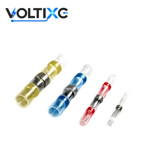
One heating step melts a solder seal wire connector’s solder ring into the overlapped strands and shrinks its sleeve onto the insulation at each end. Shops also sell it as a solder butt connector, a heat shrink solder connector or a solder sleeve splice. The SST sheet gives the wire band, sleeve size and colour. It doesn’t state the solder alloy, the sleeve material or a heating setting, so ask for all three before you specify.
| Point | What the data says | Source |
|---|---|---|
| Even heat | Heat-shrink products must be heated uniformly all the way around to achieve a good installation. | 3M, on heat-shrink products in general; not an SST setting |
| Solder preform | The majority of Raychem termination products incorporate a fluxed solder preform, described as essential for a controlled soldering process. | TE Connectivity, on its own Raychem parts; not an SST setting |
| Sleeve recovery | Heating conforms heat-shrink tubing to the size and shape of the part underneath. | TE Connectivity, on heat-shrink tubing in general; not an SST setting |
| Seal | Heat-shrink products exert no inward pressure once shrunk, so they use mastic or adhesive for environmental seals. | 3M, on heat-shrink products in general; not an SST setting |
| Clear wall | Raychem wire termination products are housed in transparent heat-shrinkable sleeves that allow inspection. | TE Connectivity, on its own Raychem parts; not an SST setting |
| Uneven heat | Uneven heat on heat-shrink materials can cause burn marks, large differences in wall thickness, and hot-melt adhesives or mastics that are not activated. | 3M, on heat-shrink materials in general; not an SST setting |
Source: 3M and TE Connectivity statements on heat-shrink parts in general, as named in each row; none of them is SST supplier data.
Strip both wires and push them in from opposite ends. The bare strands should overlap under the ring.
Keep the heat gun moving round the sleeve so no side stays cold. If one side scorches while the other hasn’t shrunk, the heat is uneven.
Hold the heat on the middle until the ring melts and runs into the strands. Then look for any part of the ring that never flowed.
Move the heat out to each end of the sleeve. You should see adhesive at both ends, since a dry end has no seal.
Let the joint cool before you bend or pull the wire. Where the wall is clear, look through it for solder in the strands before the splice goes into the loom.
VoltixC lists seven SST solder seal wire connectors in six AWG bands, from 26-24 AWG to 8-4 AWG; choose the band whose range contains the gauge of both wires you are joining. The model table repeats the supplier specification sheet row for row, with size and colour. The check table under it turns those rows into a lookup by wire gauge, and the last table lists other names shops use for the same sleeve.
| Part No. | Wire (AWG) | mm² | Length L (mm) | A (mm) | ØB (mm) | Color | Operating temp. range (°C) |
|---|---|---|---|---|---|---|---|
| SST-S11 | 26-24 | 0.25-0.34 | 26 | 1.7 | 1.0 | White | -55 to 125 |
| Model confirmed per order | 22-18 | 0.5-1.0 | 40 | 2.7 | 1.4 | Red | Confirmed per order |
| Model confirmed per order | 22-18 | 0.5-1.0 | 40 | 2.7 | 1.4 | Red | Confirmed per order |
| SST-S31 | 16-14 | 1.5-2.5 | 40 | 4.5 | 2.3 | Blue | -55 to 125 |
| SST-S41 | 12-10 | 4-6 | 40 | 6.0 | 3.7 | Yellow | -55 to 125 |
| SST-S51 | 10-6 | 6-14 | 33 | 11.5 | 5.8 | Blue | -55 to 125 |
| SST-S61 | 8-4 | 8-22 | 33 | 13 | 6.8 | Blue | -55 to 125 |
Source: supplier specification sheet for the SST solder sleeve wire splices, transcribed row by row; values are not re-measured by VoltixC.
Data note: these 7 rows are the full SST specification table. The sheet prints two 22-18 AWG models with different operating temperature ranges, and the two 22-18 rows cannot yet be matched to them, so the model and its range are confirmed per order. Letter columns follow the supplier drawing: L is the sleeve length, and A and ØB are the other two dimensions it marks. Body material and solder alloy are not on the sheet, so ask for both before you order.
| Your copper wire (AWG) | Band on the sheet that covers it | Check before you order |
|---|---|---|
| 26 or 24 | 26-24 (SST-S11, 0.25-0.34 mm²) | Smallest band on the sheet |
| 22, 20 or 18 | 22-18 (two rows, 0.5-1.0 mm²) | The sheet has two 22-18 models; ask which one is quoted |
| 16 or 14 | 16-14 (SST-S31, 1.5-2.5 mm²) | One row |
| 12 | 12-10 (SST-S41, 4-6 mm²) | One row |
| 10 | 12-10 or 10-6 (SST-S41 or SST-S51) | Both bands include 10 AWG; send the insulation outside diameter so the fit is confirmed per order |
| 8 or 6 | 10-6 or 8-4 (SST-S51 or SST-S61) | Two bands overlap here; same check as 10 AWG |
| 4 | 8-4 (SST-S61, 8-22 mm²) | Largest band on the sheet |
| Larger than 4 AWG | Not listed | Use a crimped copper splice: see copper butt splices |
The lookup table leaves these points open:
Two different gauges. Both wires must sit inside one band. A 12 AWG to 10 AWG joint fits the 12-10 band; a 14 AWG to 18 AWG joint spans two bands, so ask before you order.
More than one wire per end. The sheet does not say whether a band covers one conductor or a bundle, so state the wire count at each end.
Thick insulation. The sleeve has to recover onto the insulation on both sides, so give the insulation outside diameter when it is heavier than standard hook-up wire.
| Name used in shops and searches | What it means on this page |
|---|---|
| solder seal butt connectors, solder butt connectors, butt connectors solder, solder butt splice | This SST sleeve: two stripped wires meet end to end inside it, a butt splice made with solder |
| heat shrink solder butt connectors, heat shrink solder connectors, solder heat shrink connectors, solder connectors heat shrink | The same sleeve, named after its heat-shrink wall |
| solder shrink connectors, shrink solder wire connector, heat shrink solder wire connectors | The same sleeve; shops change the word order |
| heat shrink self solder connectors | “Self solder” means the ring is already inside, so no soldering iron is used |
| soldering butt connectors, electrical connectors with solder, heat shrink butt connectors with solder | Retail names for the same part; without the solder ring the shape is a crimp splice (see the route table) |
| wiring solder connectors | The same sleeve on low-current wiring |
| waterproof solder connectors, waterproof splice | Retail wording for the adhesive-sealed ends, not an IP rating |
| solder sleeve splice | The finished joint: the ring melted inside the shrunk sleeve, one electrical connection |
An SST solder seal connector combines a heat-shrink sleeve, a solder preform and a sealing adhesive in one part; the SST specification sheet gives sleeve sizes and colours but no material for any of the three. The table separates what each part does from where that statement comes from, so you can see which points your quote has to answer.
| Part | What it does | Where the statement comes from |
|---|---|---|
| Heat-shrink sleeve | Covers the joint to insulate it and recovers onto the insulation of both wires | SST specification sheet: length L, dimensions A and ØB and a colour for each size. According to TE Connectivity, heat-shrink tubing provides electrical insulation, mechanical protection, environmental sealing and strain relief. |
| Solder preform (ring) | Melts and joins the strands | TE describes fluxed solder preforms in its Raychem termination products. The SST alloy is not listed; ask before you order |
| Sealing adhesive | Fills the gap between sleeve and insulation | According to 3M, heat shrink relies on adhesive or mastic, not pressure, for an environmental seal. |
| Wall transparency | Shows whether the solder has flowed | According to TE Connectivity, clear heat-shrink tubing permits inspection of covered components. |
| Wall construction | Single wall or dual wall | According to TE Connectivity, its tubing comes in single-wall and dual-wall constructions for connector sealing and cable transitions. The SST wall type is confirmed per order |
Shrink ratio decides how wide a range of insulation diameters one sleeve can close onto, and the SST sheet does not state one. Two TE parts show the spread, and they are TE figures only. TE’s DR-25-1/8-0-SP tubing has a 2:1 shrink ratio, a 3.2 mm minimum expanded inside diameter and a 1.6 mm maximum recovered inside diameter. TE’s dual-wall ES2000-NO.1-C1-0-STK tubing has a 4:1 ratio, 5.72 mm expanded and 1.27 mm recovered. Neither part is an SST sleeve; ask for the SST ratio and recovered diameter when your insulation is thicker or thinner than the band suggests.
Ask as well whether the solder alloy is lead-free before you order; the specification sheet does not say.
Heat solder seal wire connectors evenly around the full circumference until the solder ring has flowed and both ends of the sleeve have closed onto the insulation. The SST size table gives no heating temperature and no heating time, so ask for the heating method for your band before you order.
Put the sleeve on one wire. Push both stripped ends in until the strands overlap under the ring, then hold the wires still.
A heat gun with a reflector nozzle reaches the whole sleeve; a flame heats one side only.
Keep the heat moving around the sleeve; according to 3M, heat-shrink products must be heated uniformly all the way around.
The solder has run into the strands and adhesive shows at both ends? Stop there, and let the joint cool before you bend or pull the wire.
Check through the wall. If you see an unmelted ring, a dry end or a scorched patch, cut the splice out and make it again.
Pick solder seal wire connectors when you want the joint and its sealed cover made in one heating step on wire from 26 to 4 AWG. Pick a crimped splice when the joint has to hold without the solder, when no heat source can reach the work, or when the cable is heavier than 4 AWG. Butt connectors with solder in the sleeve are this page’s product; without the solder ring, the same shape is a crimp splice. The routes below are the other splice and termination pages in the VoltixC range of crimp connectors.
| Route | How the joint is made | Where it fits | Page |
|---|---|---|---|
| Solder seal wire connectors (this page) | Solder ring and heat-shrink sleeve, one heating step | Inline wire-to-wire splices, 26-24 to 8-4 AWG as listed | This page |
| Insulated crimp splices | Crimped barrel inside a vinyl insulation sleeve, made with crimpers | Splices made with a crimp tool and no heat source; closed-end joints | insulated butt splices |
| Heat-shrink crimp splices | Crimped barrel under a heat-shrink sleeve, no solder ring | Joints that need a crimp for strength and a shrunk cover on top, for example where damp could start corrosion | heat shrink butt connectors |
| Bare copper compression splices | Crimped copper tube, no insulation | Cable heavier than the SST range; the splice is covered separately | non insulated butt connectors |
| Terminal to a stud | Crimped ring terminal, not a splice | Wire ending on a stud or screw, not on another wire | insulated ring terminals |
When to leave this page for another route:
Boat wiring. According to West Marine, ABYC E-11 states that solder shall not be the sole means of mechanical connection in a marine circuit. A solder seal joint holds by solder alone, so a marine circuit calls for a crimped splice; the heat-shrink crimp route keeps a sealed cover as well. VoltixC does not state ABYC compliance for any SST size.
No heat at the work site. A vinyl crimp splice needs only the crimp tool.
Cable above 4 AWG. Above the 8-4 AWG band there is no SST listing, so heavier cable moves to a bare copper compression splice.
Heavier sealing wall. According to TE Connectivity, heat-shrink tubing is made in single-wall and dual-wall forms for connector sealing. If your specification calls for a dual wall, confirm the SST wall type before you order, or use a separate dual-wall cover.
Switching routes changes what you send: a crimp splice quote needs the barrel size and the tool you use, while an SST quote needs only the wire gauges, the count per band and the heating method you plan to use.
Solder seal wire connectors fit inline wire-to-wire splices from 26 to 4 AWG where a heat source can reach all of the sleeve. They are the wrong part for marine circuits, for cable heavier than 4 AWG and for a wire that ends on a stud. The cards are worked out from how the sleeve is built and from the sources cited; VoltixC order records are not their basis.
Needs: fine wire that must stay whole, so the strands are joined by solder instead of a crimp barrel.
Fails when: the heat source is too large for the sleeve and scorches the thin insulation next to it.
Needs: both wires in one band and enough free wire on each side to slide the sleeve clear before heating.
Fails when: the two wires come from different bands, such as 14 AWG to 18 AWG.
Needs: adhesive melted at both ends, because according to 3M a shrunk sleeve exerts no inward pressure and the seal comes from mastic or adhesive.
Fails when: one end stays dry. VoltixC has not tested any SST size to an IP rating, so a rated enclosure or a tested splice is the route when a rating is required.
Needs: the right band where two bands overlap at 10, 8 and 6 AWG, and a heat source that can bring a larger ring to full flow.
Fails when: the ring melts on the outside only; check through the wall before the splice goes into service.
According to West Marine, ABYC E-11 does not accept solder as the sole means of mechanical connection in a marine circuit. Use a crimped splice, with a heat-shrink cover if the joint needs sealing.
The SST sheet stops at the 8-4 AWG band (8 to 22 mm²). Battery and power cable above that size goes to bare copper compression splices, which are crimped copper tubes.
A splice joins two wires. A wire that ends on a stud needs a terminal such as insulated ring terminals instead.
VoltixC is UL certified, holds a CE attestation that covers the full terminal range, and has a RoHS test report available (SGS); certificate numbers and dates are not printed on this page. All three documents are issued to Guangzhou FuTeXin Technology Co., Ltd., the company behind the VoltixC brand. The CE attestation is under the Low Voltage Directive 2014/35/EU with EN 60947-7-1, EN 60947-7-2 and EN 60947-7-3. The SGS report tested lead, mercury, cadmium and hexavalent chromium on tin-plated copper terminal samples, so ask whether it extends to the solder and sleeve of your SST band.
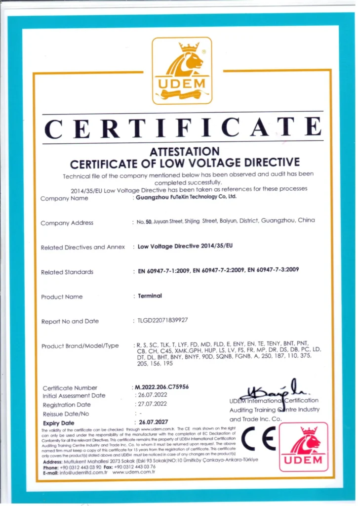
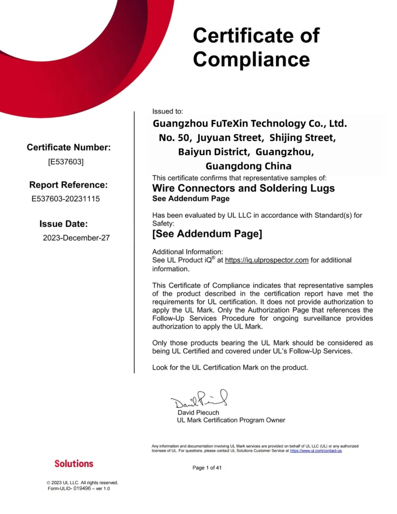
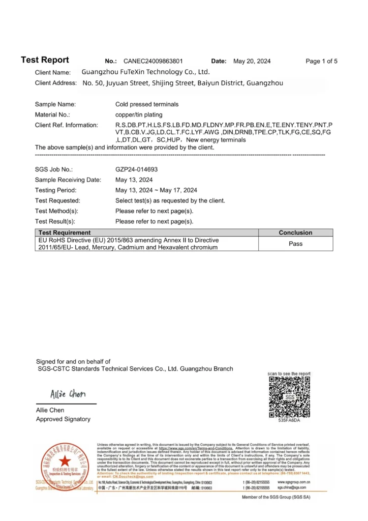
These six photos record machines at the Guangzhou site; they say nothing about how an SST sleeve is made or checked. Which checks, if any, apply to an SST order is agreed with the quote.






Put these five questions to any solder seal supplier before the first SST order:
| Question | What the answer tells you |
|---|---|
| Heating instructions for each band you order | The size table gives an operating range, not a heat-gun temp or a heating time |
| The solder alloy, and whether it is lead-free | The specification sheet does not state the alloy |
| Whether the SGS RoHS report and the UL addendum cover your band | The SGS samples were tin-plated copper terminals, not solder sleeves |
| Which 22-18 AWG model you are quoted | The sheet has two 22-18 models with different operating ranges |
| A sample of each band before the main order | Samples show the ring, the adhesive and the fit on your own wire |
The price of an SST solder seal connector order moves with the bands you choose, the quantity per band, the packing and any change to the sleeve itself; MOQ, payment terms, warranty and lead time are confirmed per order by email or the enquiry form. None of those terms is fixed on this page.
| Driver | Effect on cost | What you control |
|---|---|---|
| Number of bands | Each band is a separate line to set up and pack | List only the bands your wiring uses |
| Quantity per band | Larger runs spread the setup of each line | Give a quantity for every band, not one total |
| The two 22-18 AWG rows | The sheet has two 22-18 models with different operating ranges | Ask which model is quoted and choose one |
| Sleeve colour or print | The sheet gives one standard colour per size; a change adds a step | Accept the standard colour or name the one you need |
| Packing and labels | Bulk bags, counted boxes and printed labels differ in labour; a retail-style connector kit that mixes sizes is quoted as separate band lines | State the count per bag or box and the label text |
| Samples before the order | Sampling adds a short run for each band | Ask for samples only of the bands you have not used before |
| Drawing-based changes | A new sleeve length or ring size needs tooling, confirmed per order | Send a drawing only when a listed band cannot do the job |
| Destination and documents | Shipping terms and paperwork vary by market | Name the destination country and any document you need |
Sample timing for a listed band starts at 7 days, and the schedule for the main order is agreed after the quote. The form on the quote page has eight fields: name, company, email, country, product line, conductor size, quantity and message. It has no upload field, so drawings and photos of the wire ends travel by email to hugo@voltixconnect.com.
A useful enquiry for solder wire connectors lists each gauge pair, the quantity for each band and the packing. With those three items the reply can name the SST reference for every line.
Keep one band per line, so the quote can be set against your own size list row by row. Gauges outside the listed bands, such as cable above 4 AWG, are not quoted as SST sleeves.
No size tool covers solder seal sleeves yet, so four guides carry the checks around this product: installing the sleeve, telling connector types apart, the crimp families, and crimping method.
Installing a solder seal sleeve step by step, and how to check the finished splice.
How solder, crimp and other wire connector types compare, and where each one belongs.
The main families of crimp terminals and splices, compared by what they connect.
Tool and die choice, strip length and the pull check, for when you move to a crimped splice.
The seal comes from adhesive that melts at each end of the sleeve and fills the gap around the wire insulation. According to 3M, a heat-shrink product exerts no inward pressure after shrinking, which is why mastic or adhesive does the sealing. VoltixC has not run an IP or water test on any SST size.
Strip both wires, push them into the sleeve until the strands overlap under the solder ring, then heat the sleeve evenly all the way round. According to 3M, heat-shrink products need uniform heat around the whole circumference for a good installation. Stop when the ring has flowed and both ends have closed; the SST size table gives no heating temperature or time, so ask for the heating method before you order.
Seven rows on the SST specification sheet cover six AWG bands, 0.25 to 22 mm²: 26-24, 22-18 (two rows), 16-14, 12-10, 10-6 and 8-4 AWG. The single-row bands carry part numbers SST-S11, SST-S31, SST-S41, SST-S51 and SST-S61; the 22-18 model is confirmed per order. Values are per supplier specification sheet and are not re-measured.
A lighter heats one side of the sleeve, which works against an even installation. According to 3M, uneven heat on heat-shrink materials can cause burn marks, uneven wall thickness and adhesive that is not activated. Use a heat source that reaches the whole sleeve.
“Waterproof” in retail titles for solder wire connectors refers to the adhesive seal at the sleeve ends, so a waterproof splice here means sealed ends, not a rating. TE Connectivity lists environmental sealing among the jobs heat-shrink tubing does. VoltixC has not run an IP or immersion test on SST sleeves; ask before you specify one.
Not as the only joint in a marine circuit. According to West Marine, ABYC E-11 does not allow solder as the sole means of mechanical connection there. A marine grade label on a solder seal pack does not change this. Use a crimped splice, and a heat-shrink crimp splice if the joint also needs a sealed cover.
Yes, when both gauges fall in the same listed band. A 12 AWG wire to a 10 AWG wire fits the 12-10 band (SST-S41); a 14 AWG wire to an 18 AWG wire spans two bands, so ask before you order.
No. The largest SST band is 8-4 AWG (SST-S61), and nothing above it is on the sheet. For heavier cable, a bare copper compression splice from the non-insulated range is the route.
They suit small inline splices that a heat source can reach and that do not rely on the solder alone to hold under load. One heating step gives both the solder joint and a sealed cover, and according to TE Connectivity, clear heat-shrink tubing permits inspection of the covered part. For marine circuits and cable above 4 AWG, a crimped splice is the better route.
The SST specification sheet does not name the solder alloy, so the sheet alone cannot answer it. Ask for the alloy of each band before you order. A RoHS test report is available (SGS), but its samples were tin-plated copper terminals, so ask whether it covers the solder in your band.
No. The sizes, colours and operating ranges come from the supplier specification sheet and have not been re-measured by VoltixC. Wall type is confirmed per order for the band you choose; the alloy is not on the sheet, so ask before you order.
Three lines of information open an SST quote: