VOLTIXC / ENQUIRY
Request a Quote
Tell us what you need and we will review your enquiry.

By VoltixC Engineering Team · Last updated: 2026-09-28
Fast answer: To use a solder seal wire connector, strip and overlap the two wire ends, centre the solder ring over the bare strands, then heat the sleeve evenly with a heat gun from the middle outward until the solder flows into the strands and adhesive appears at both ends. Let the joint cool before a gentle pull test.
A solder seal wire connector is a short, clear heat-shrink sleeve with a ring of solder in the middle and a ring of adhesive near each end. Heating it shrinks the sleeve onto both wire jackets, melts the solder into the overlapped strands and closes each end with adhesive. Shops also sell the part as a solder sleeve or a heat shrink solder butt connector. VoltixC lists its SST range of solder seal wire connectors in six bands, from 26-24 AWG up to 8-4 AWG.
A solder seal joint suits an inline splice on stranded wire, where a heat gun can reach the whole sleeve. Marine circuits, cable heavier than 4 AWG and wires that end on a stud call for a crimped part. You will find no heating temperature on this page, because the SST size table gives none.
Before you strip anything, confirm that the AWG band on the pack covers both wires, that your heat gun can reach the whole sleeve and that the solder ring will sit over bare copper.
| Check | What to confirm | Covered in |
|---|---|---|
| Connector family | SST solder-seal butt connector: a heat-shrink sleeve with a solder ring, made for inline wire-to-wire splices | What is inside |
| Wire bands | Seven rows on the SST specification sheet in six bands: 26-24, 22-18 (two rows), 16-14, 12-10, 10-6 and 8-4 AWG, or 0.25 to 22 mm²; both wires have to fall inside one band | Tools and prep |
| Band colour | One sleeve colour per band on the SST sheet: white 26-24, red 22-18, blue 16-14, yellow 12-10 and blue again for 10-6 and 8-4; other makers use their own colours, so read the AWG range printed on the pack | Tools and prep |
| Solder alloy | Not stated on the SST specification sheet; ask whether it is lead-free before you order | Choosing for a volume order |
| Heat source | A heat gun with a reflector nozzle; 3M states that heat-shrink products must be heated uniformly all the way around to achieve a good installation | Step by step |
| Heating setting | None given here: the SST size table states no heating temperature and no time, so ask for the heating method for your band | Step by step |
| Strip length | Enough bare copper for the two ends to overlap under the solder ring, with insulation inside each end of the sleeve | Step by step |
| Shrink ratio | Not stated for SST; as TE examples, the DR-25-1/8-0-SP tube has a 2:1 shrink ratio, 3.2 mm minimum expanded ID and 1.6 mm maximum recovered ID and the dual-wall ES2000-NO.1-C1-0-STK has 4:1, 5.72 mm and 1.27 mm | Choosing for a volume order |
| Finished joint | Solder drawn into the strands and adhesive at both ends; clear heat-shrink tubing permits inspection of covered components, per TE Connectivity | Inspecting the joint |
Source: SST rows per supplier specification sheet, not re-measured by VoltixC; other rows from the sources cited below.
Rows that say “ask” have no SST value behind them. The two TE tubes show how far shrink ratios spread between parts and set no figure for an SST sleeve.
| Also asked as | Short answer | Covered in |
|---|---|---|
| how to use solder seal wire connectors; solder seal wire connectors how to use; how to use solder butt connectors | Overlap the stripped ends under the solder ring, then heat from the middle out until adhesive shows at both ends | Step by step |
| how to solder wire connectors; how to solder a wire to a connector | With an iron: tin the wire, melt solder in the connector’s cup and push the wire to the bottom | Iron and solder cup |
| how to solder electrical connections | Wire to wire: slide heat-shrink tube on first, twist the strands, solder them with an iron and shrink the tube over the joint | Iron and solder cup |
| crimp vs solder; butt connector vs solder | A crimp for boat wiring and for cable above 4 AWG; a solder seal sleeve for small dry splices that a heat gun can reach | Which method fits |
| soldering crimp connectors; soldering wire terminals | Crimp them with the right die and ask the terminal maker before adding solder; the VoltixC range is on the crimp connectors page | Iron and solder cup |
| are solder seal wire connectors waterproof | Adhesive closes both ends of the sleeve, which is why shops call them waterproof; this guide gives no protection rating | What is inside |
| what is inside the solder sleeve | Inside the solder sleeve sits one solder ring in the middle and an adhesive ring near each end | What is inside |
| how to tell the solder has flowed | Look through the clear wall: the ring outline is gone and the strands look silver | Inspecting the joint |
| solder seal connectors for wire harness work and wiring repairs | Any splice a heat gun can reach all round; for a harness with many wires, quote each band as its own line with the SST part numbers | Choosing for a volume order |
A solder seal connector is a clear heat-shrink tube with a solder ring in the middle and an adhesive ring near each end.
| Problem | What to do | Check |
|---|---|---|
| You want to know which part does what | Look through the tube before heating: the band of solder sits at the centre and a softer ring of adhesive sits toward each end | Both rings are visible through the wall of a new sleeve |
| The tube has to close onto the wire | Heat it until it recovers; according to TE Connectivity, heating conforms the tubing to the size and shape of the part underneath | The tube lies tight on both jackets with no loose length |
| The solder has to join the strands | Hold the heat on the middle until the ring melts. TE builds a fluxed solder preform into the majority of its Raychem termination products and calls it essential for a controlled soldering process | No outline of the ring is left; the strands look silver |
| The ends have to seal | Move the heat out to each end so the adhesive melts. A shrunk sleeve exerts no inward pressure, so 3M’s heat-shrink products rely on mastic and adhesive for environmental seals | A thin bead of adhesive shows at both ends |
| The finished joint needs a cover | Leave the recovered tube in place as the joint’s outer layer; TE lists electrical insulation, mechanical protection, environmental sealing and strain relief among the jobs heat-shrink tubing does | No bare copper shows anywhere along the joint |
| You only have plain heat-shrink tube | Join the wires first with a crimp or an iron, and slide the tube on before the joint is made | The tube covers the finished joint with overlap onto both jackets |
Plain heat-shrink tube carries no solder and no adhesive rings, so it covers a joint without making one. The SST listing names a heat-shrink sleeve but gives neither the solder alloy nor the sleeve material; ask for both before you order.
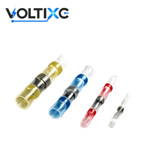
Use a solder seal sleeve when you want the solder joint and its sealed cover from one heating step.
| Method | What you need | How the joint holds | Cover over the joint | Where it fits | VoltixC page |
|---|---|---|---|---|---|
| Solder seal sleeve | Heat gun and wire stripper | Solder from the ring, drawn into the overlapped strands | The same sleeve, closed at both ends by adhesive | Inline splices from 26-24 to 8-4 AWG that a heat gun can reach all round | SST solder seal sleeves |
| Soldering iron, wire to wire | Iron, solder, stripper and a separate piece of heat-shrink tube | Solder melted by the iron into twisted strands | Heat-shrink tube slid on before the joint is made | Repairs where no sleeve of the right band is at hand | Not a connector; no product page |
| Soldering iron, solder cup | Iron, solder and isopropyl alcohol for cleaning | Solder melted inside the connector’s cup around the wire | The boot or tube the connector maker specifies | Connector pins made with solder cups | Not in the VoltixC range |
| Crimp butt connector, vinyl insulated | Stripper and a ratchet crimper with the right die | One crimp on each half of a metal barrel | Vinyl sleeve over the barrel, open at the ends | Dry splices and jobs specified as crimped | insulated butt splices |
| Heat-shrink crimp splice | Stripper, crimper and heat gun | One crimp on each half of a metal barrel | Heat-shrink sleeve recovered over the crimp | Crimped joints that also need a shrunk cover | heat-shrink crimp splices |
| Job | Pick | Why |
|---|---|---|
| Boat wiring | A crimped splice, in the heat-shrink crimp version when the joint needs a sealed cover | West Marine reports that solder shall not be the sole means of mechanical connection in a marine circuit under ABYC E-11.16.3.7, and a solder seal joint holds by its solder alone |
| Cable heavier than 4 AWG | A crimped copper compression splice | No SST band goes above 8-4 AWG |
| Job specification says crimped | A crimp butt connector in the right band | The specification sets the joint type |
| Connector pin with a solder cup | A soldering iron | The cup is built to take solder from an iron |
| Dry bench splice, 26-24 to 16-14 AWG, heat gun at hand | A solder seal sleeve | The cover comes with the joint, so there is no separate tube to slide on first |
On a bench job with 18 or 16 AWG wire we would pick the sleeve whenever a heat gun is already out. With a crimper and a box of vinyl splices there instead, crimp vs solder becomes a question of which kit is on the bench. The crimp route is in how to use butt connectors, and wire connector types compares splices, terminals and caps.
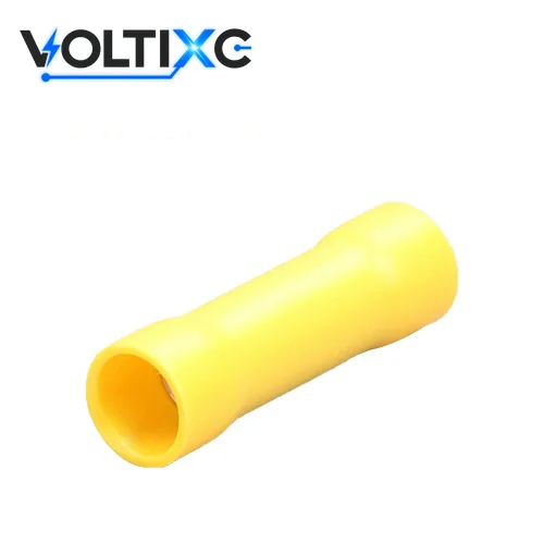
You need a heat gun, a wire stripper and an SST band that covers both wires, plus ventilation and eye protection at the bench.
| Item | What it does | What to check |
|---|---|---|
| Heat gun with a reflector nozzle | Wraps heat around the sleeve; according to 3M, heat-shrink products must be heated uniformly all the way around to achieve a good installation | Heat reaches the far side of the sleeve without your turning the joint over |
| Wire stripper | Takes the jacket off cleanly | Every strand comes out whole, with no nick in the copper |
| SST sleeve of the right band | Carries the solder and adhesive for one joint | Both wire gauges sit inside the band printed on the pack |
| A clamp or a rest for the wires | Keeps the joint still while it heats and cools | The wires stay where they are when you let go |
| Ventilation and safety glasses | Clears solder and flux fumes and guards your eyes from hot solder | Air moves across the bench and the glasses are on |
| Clean, dry wire ends | Lets the solder wet the strands | Bright copper with no oil, paint or corrosion |
| Strip length | No printed value for SST sleeves; lay the sleeve along the wire, mark where the solder ring falls and strip to that mark | The two bare ends overlap under the ring and each jacket stays inside the sleeve |
| Your wire (AWG) | SST band that covers it (part no., mm²) | Check before heating |
|---|---|---|
| 26 or 24 | 26-24 (SST-S11, 0.25-0.34 mm²) | The smallest band on the sheet |
| 22, 20 or 18 | 22-18 (0.5-1.0 mm²) | Two rows on the sheet; the part number is confirmed per order |
| 16 or 14 | 16-14 (SST-S31, 1.5-2.5 mm²) | One row |
| 12 | 12-10 (SST-S41, 4-6 mm²) | One row; a 12 AWG wire can join a 10 AWG wire in this band |
| 10 | 12-10 or 10-6 (SST-S41 or SST-S51) | Both bands include 10 AWG; the jacket diameter decides |
| 8 or 6 | 10-6 or 8-4 (SST-S51 or SST-S61) | Two bands overlap here; measure the jacket |
| 4 | 8-4 (SST-S61, 8-22 mm²) | The largest band on the sheet |
| Heavier than 4 | No SST band | A crimped copper splice, as on the copper compression butt splice page |
Source: per supplier specification sheet (SST series); not re-measured by VoltixC.
Spec note: Band colours on solder seal sleeves vary by maker. Match the AWG range printed on the pack to both wires, and quote each wire gauge when you ask for SST sizes.
For wire sized in mm², convert it with the cable lug size chart before you pick a band.
A solder seal splice is made by heating the sleeve from the middle outward once the overlapped strands sit under the solder ring, and it is finished when adhesive shows at both ends.
Strip each wire so that the two bare ends can overlap under the solder ring.
Every strand should come out whole, with no nick in the copper.
The stripped ends go into the sleeve from opposite sides, with the strands crossing each other.
Through the clear wall you can see the two ends overlapping.
Slide the sleeve until the solder ring sits over the middle of the overlap.
If the ring rests on insulation, the solder has no strands to flow into.
Heating starts at the centre, with the heat gun moving around the sleeve instead of resting on one side.
The tube shrinks evenly, and a scorched side next to a loose side means the heat stayed in one place.
When the ring turns bright and runs into the strands, carry the heat out to each end.
Stop there once adhesive shows at both ends.
Let the joint cool without moving it, then pull each wire gently.
If a wire moves or the sleeve has split, cut the joint out.
3M gives the rule behind step 4: heat-shrink products must be heated uniformly all the way around to achieve a good installation. The SST size table sets no heating temperature or time for any band, so ask for the heating method for your band when you order.
Tip: Rest the wires on the bench or in a clamp before the heat goes on. Solder that sets while a wire is still moving can leave a dull, weak joint that has to be cut out.
With an iron, the heat goes into the solder cup and the melted solder in the cup takes the tinned wire, so the iron never works on the solder directly.
| Stage | What to do | Check |
|---|---|---|
| Clean the cup | Wipe the cup and the pin with isopropyl alcohol | No oil or old flux left in the cup |
| Strip and twist | Strip the wire to the depth of the cup and give the strands a light twist in their own lay | No stray strand sticks out |
| Tin the iron | Melt a little solder onto the clean tip | The tip is bright and wet all over |
| Tin the wire | Heat the strands with the iron and feed solder into them | Solder has soaked through; the strands stay flexible above the tinned length |
| Load the cup | Drop a short, pre-cut piece of solder into the cup | The piece sits inside the cup |
| Heat the cup | Hold the iron on the outside of the cup until the solder inside melts | The solder has a liquid, shiny surface |
| Insert the wire | Push the tinned wire to the bottom of the cup, against its wall | The wire bottoms out and the solder flows round it |
| Hold and cool | Keep the wire still until the solder sets, then pull it gently | A smooth, shiny fillet; the wire does not move |
| Clean again | Wipe the flux residue away with isopropyl alcohol | No sticky residue on the pin |
Two bare wires with no connector take the same idea: twist the strands together, solder them with the iron and cover the joint with heat-shrink tube. Slide that tube onto one wire before you twist, because it will not pass the joint afterwards.
Soldering crimp connectors is a separate question. A crimp terminal is built to hold by its crimp, so crimp it with the right die, as in how to crimp wires, and ask the terminal maker before you add solder to the barrel. The same applies to soldering wire terminals such as rings and spades.
A good joint shows solder drawn into the strands, an unscorched tube and adhesive at both ends; a joint with the solder still in a ring, a scorched tube or a dry end gets cut out and made again.
| Problem | What to do | Check |
|---|---|---|
| The solder still sits as a ring around the strands | Reheat the centre evenly; if the tube is fully shrunk and the ring still has not flowed, cut the joint out | Silver solder fills the strands under the wall; according to TE Connectivity, clear heat-shrink tubing permits inspection of covered components |
| The tube has burn marks or a scorched patch | Cut the joint out and make a new one with the heat gun kept moving; 3M lists burn marks, significant insulation wall-thickness differences and hot-melt adhesives or mastics that are not activated as results of uneven heat | The new tube is one even colour all round |
| One end shows no adhesive | Bring the heat back to that end for a moment; remake the joint if the adhesive still does not flow | A bead of adhesive at both ends |
| The solder looks dull or grainy, or a wire moved while it cooled | Cut it out and make it again, holding the wires still until the solder sets | The solder surface is smooth and shiny |
| A wire slips during the gentle pull | Remake the joint after checking that both wires sit inside the band | Both wires hold by hand |
| The joint was bent while still warm | Keep new joints straight until they cool; 3M warns that a heat-shrink accessory must not be bent after installation because bending can compromise the seal | The sleeve is straight and sealed at both ends |
| You cannot see the solder through the wall | Use sleeves with a clear wall. TE houses its Raychem wire termination products in transparent heat-shrinkable sleeves that allow inspection and can provide environmental protection, as its SolderSleeve page describes | The ring and the strands are visible before and after heating |
Redoing a joint means cutting the whole sleeve out and stripping fresh ends, because a scorched sleeve stays scorched after a second heating. This guide sets no pull-force value; the hand pull only shows whether a wire moves.
Caution: A scorched or split sleeve stays damaged after it cools. Cut the joint out and start again with a new sleeve.

For a volume order, compare solder seal connectors by wire band, solder alloy, shrink ratio, wall type, adhesive and a clear wall, and ask for each value the listing leaves blank.
| Parameter | Why it matters | SST listing and what to ask |
|---|---|---|
| Wire band | Both wires have to fit one band | Six bands from 26-24 to 8-4 AWG (0.25 to 22 mm²), per supplier specification sheet |
| Band colour | Colours are one maker’s code | SST sheet: white, red, blue or yellow by band, with blue on three bands; check the AWG range |
| Solder alloy and lead-free status | Decides whether the part meets your material rules | Not stated; ask before you order |
| Shrink ratio | Sets how wide a range of jacket diameters one sleeve closes onto; TE’s DR-25-1/8-0-SP example has a 2:1 shrink ratio and its dual-wall ES2000-NO.1-C1-0-STK example a 4:1 ratio | Not stated; ask for the ratio and the recovered diameter |
| Wall construction | Changes how the sleeve seals; TE makes heat-shrink tubing in single-wall and dual-wall constructions for connector sealing, breakouts and connector-to-cable transitions | Not stated; confirmed per order |
| Adhesive rings | Seal each end of the sleeve | Not listed as a separate field; check both ends on a sample |
| Clear wall | Lets you see the solder flow | Check it on a sample |
| Samples per band | Show the ring, the adhesive and the fit on your own wire | Fastest sampling is 7 days |
Buyers ask which solder seal connectors are best. For a volume order the answer sits in this table. Each band is quoted as its own line, and one sample per band, heated on your own wire, shows how the ring and the adhesive behave.
The RoHS image below is the first page of an SGS test report VoltixC holds. Its samples were tin-plated copper terminals, so ask about the solder alloy directly.
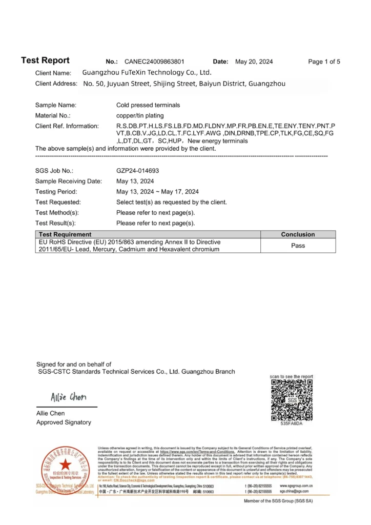
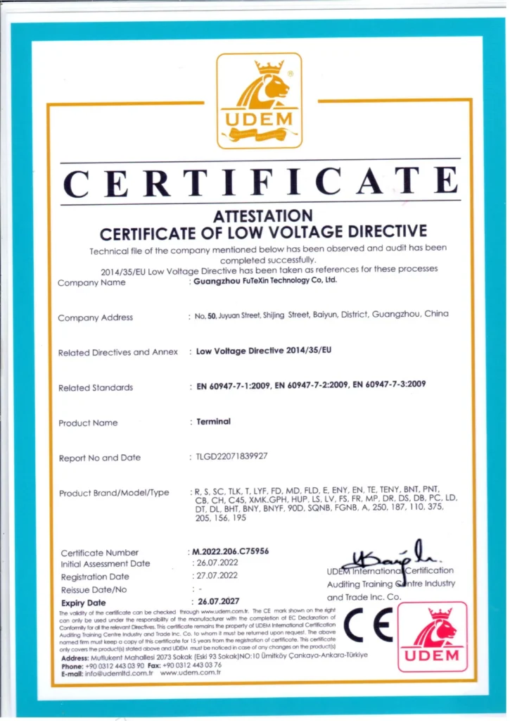
VoltixC lists seven SST solder seal connectors in six AWG bands, from 26-24 AWG to 8-4 AWG, with the 22-18 AWG band listed twice.
| Part No. | Wire range (AWG) | mm² | Sleeve length L (mm) | Colour |
|---|---|---|---|---|
| SST-S11 | 26-24 | 0.25-0.34 | 26 | White |
| Model confirmed per order | 22-18 | 0.5-1.0 | 40 | Red |
| Model confirmed per order | 22-18 | 0.5-1.0 | 40 | Red |
| SST-S31 | 16-14 | 1.5-2.5 | 40 | Blue |
| SST-S41 | 12-10 | 4-6 | 40 | Yellow |
| SST-S51 | 10-6 | 6-14 | 33 | Blue |
| SST-S61 | 8-4 | 8-22 | 33 | Blue |
Source: per supplier specification sheet (SST series, 7 rows); not re-measured by VoltixC. The sheet prints two 22-18 AWG models, and the two 22-18 rows are not yet matched to them, so that part number is confirmed per order.
The sheet gives each band a sleeve length and a colour. Body material and solder alloy are not on it, so ask for both with the quote. Cable above 4 AWG has no SST band; it moves to a crimped copper splice on the bare copper butt splice page.
An enquiry that names the gauge of each wire pair, the quantity per band and the packing lets the reply give an SST reference for every line. The full size table sits on the SST product page.
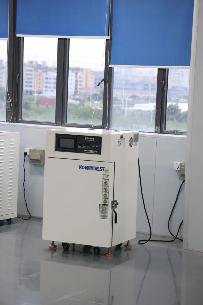

The two photos show machines on the Guangzhou site and describe no SST test.
Don’t. A lighter puts a small, hot flame on one side of the sleeve; that side scorches while the far side stays loose, and the adhesive at the ends may never melt. Use a heat gun, and cut out any sleeve that has already scorched.
Look through the wall. When the ring has flowed you can’t see its outline any more, and the strands under it turn silver along the whole overlap. On the small 26-24 AWG sleeve the ring is thin, so a magnifier makes the check easier.
No, cross them. Each stripped end goes in from its own side of the sleeve and the strands overlap under the ring. Twist two 18 AWG ends together first and the lump can sit off to one side of the ring, where the solder reaches only part of it.
Both ends are sealed. A shrunk sleeve exerts no inward pressure, which is why 3M’s heat-shrink products use mastic and adhesive for environmental seals. If one end of a 16-14 AWG joint stays dry, bring the heat back to it briefly and remake the joint when the adhesive still does not flow.
Boat wiring is the main case. Under ABYC E-11.16.3.7, as West Marine reports, solder shall not be the sole means of mechanical connection in a marine circuit. Cable above the 8-4 AWG band has no SST sleeve at all, and how to use butt connectors covers the crimp route.
Cut it out and start over with a new sleeve from the same band, another 12-10 for a 12 AWG pair. Strip fresh ends once the wires have cooled. Reheating a scorched or unfilled sleeve won’t fix it.
For small splices, yes. You get the solder joint and a sealed cover from one heating, and the clear wall shows you whether the solder went in. We’d still crimp anything on a boat or above 4 AWG.
How this guide was written: it follows one solder seal splice from choosing the band to checking the joint. The sources are TE Connectivity’s heat-shrink tubing and SolderSleeve pages, a 3M article on heat-shrink and cold-shrink installation, and West Marine’s summary of ABYC E-11. VoltixC ran no tests for this guide and gives no heating temperature, time or pull-force figure. SST bands, part numbers, sleeve lengths and colours come from the supplier specification sheet and have not been re-measured.
VoltixC is the brand of Guangzhou FuTeXin Technology Co., Ltd. It makes the SST solder seal sleeves and the crimp butt splices this guide describes; soldering irons and heat guns are outside its range.