VOLTIXC / ENQUIRY
Request a Quote
Tell us what you need and we will review your enquiry.

By VoltixC Engineering Team · Last updated: 2026-09-28
Fast answer: Spade connector types split into two different parts: fork (spade) terminals that slide under a screw or stud, and push-on blade terminals that plug into a receptacle. For a fork, match the wire range to the barrel and the fork opening to the stud size; push-on parts are chosen by tab width and thickness instead.
Hold the part up and look at the tongue. A fork terminal has a flat tongue split into two prongs, with a crimp barrel behind it, and it clamps under a screw head or a nut on a stud. A push-on blade has no prongs at all: it is a flat male tab or a female receptacle that grips the tab, and nothing gets screwed down. Sellers file both under “spade connector”, so one spade connector sizes chart may list forks while the next lists receptacles. VoltixC makes the fork kind as insulated spade terminals in vinyl and nylon, and the push-on kind as quick disconnect terminals.
For a buyer, a spade connector is a crimp terminal with a flat tongue, and the hardware it lands on decides which of the two it has to be. From here on, “fork” means the screw-mounted part and “push-on blade” the plug-in part. Tongue shape, sleeve, wire band and stud size decide which fork fits; tab width and thickness size a push-on part, and the female spade connector sizes guide covers that side.
Check how the part mates before anything else: a fork clamps under a screw or stud nut, a push-on blade slides onto a flat tab, and each one is then sized by different fields.
| Point | Fork (spade) terminal | Push-on blade (quick disconnect) |
|---|---|---|
| How it mates | Clamped flat under a screw head or a stud nut | Burndy describes a female quick disconnect with a receptacle front end that slides onto and off a male blade |
| Fitting and removal | Per ABB’s Sta-Kon catalogue, fork terminals can be installed without completely removing the mounting screw | Pushed onto the tab and pulled off it; no screw is involved |
| Sized by | Wire band first, then stud or screw size | Wire band first, then tab width and thickness |
| Standard tab widths | Not used for forks | UL 310 applies to quick-connect terminals, both connectors and tabs, with nominal widths of 2.8, 3.2, 4.8, 5.2 and 6.3 mm (0.110, 0.125, 0.187, 0.205 and 0.250 in) |
| Wire bands VoltixC lists | 22–16, 16–14 and 12–10 AWG (0.5–6 mm²) in vinyl (SV) and nylon (SNY); 14–12 AWG in vinyl only | 22–16, 16–14 and 12–10 AWG across six vinyl and nylon series |
| Stud or tab fit | Studs #4 to 5/16 in on the SV and SNY sheets, stud hole d2 3.2 to 8.4 mm | Each part number takes one tab width; match it to your mating tab |
| Sleeve colour | Waytek’s example code is red 22–18, blue 16–14 and yellow 12–10 AWG; other makers set other ranges | The same colour idea; read the maker’s own chart |
| VoltixC colour and body | Tinned copper body on every SV and SNY part; SV sleeves red 22–16, blue 16–14, black 14–12 and yellow 12–10 AWG; SNY prints red, blue and yellow die colours for its three bands | Colour by wire band, listed per part number on the quick disconnect page |
| VoltixC page | SV and SNY spade terminal range | push-on terminal range |
Source: VoltixC rows per supplier specification sheet (SV and SNY spade series, quick disconnect series), not individually re-tested; other rows from the sources cited below.
A part that matches neither column is a different family. Closed eyes belong with ring terminal sizes, and round pin-and-socket parts with how to crimp bullet connectors.
| Also asked as | Short answer | Covered in |
|---|---|---|
| what is a spade terminal | A crimp terminal with a flat tongue; sellers use the name for screw-mounted forks and for push-on blades | What is a spade connector (next section) |
| what are spade connectors | The same two parts: a fork for a screw or stud, or a push-on blade for a flat tab | What is a spade connector (next section) |
| spade vs bullet connectors | A fork clamps under a screw; a bullet joins two wires in line with a round pin and socket | FAQ |
| spade terminal sizes; spade connector dimensions; spade electrical connector sizes | Wire band in AWG and mm², stud size and stud hole d2 for a fork; tab width for a push-on blade | Sizing section |
| spade connector size chart; spade terminal size chart | The AWG wire band and stud table built from the SV and SNY supplier specification sheets | Sizing section |
| insulated spade connectors | Forks whose vinyl (SV) or nylon (SNY) sleeves insulate the barrel; bare forks are not on the current list | Insulation section |
| how to connect spade connectors | Strip, insert, crimp with a crimping tool, pull-test, then clamp under the screw; the same five steps fit most electrical projects | Connection steps |
A spade connector is a crimp terminal with a flat tongue, and sellers use the name for screw-mounted forks and for push-on blades alike.
| Problem | What to do | Check |
|---|---|---|
| A listing says “fork”, “fork tongue”, “horseshoe” or “U connector” | Treat it as a fork terminal that clamps under a screw or stud; VoltixC lists these as SV and SNY fork terminals | The tongue ends in two prongs with an open gap between them |
| A listing says “push-on”, “quick disconnect”, “faston” or “blade” | Treat it as a push-on part and go to the male and female push-on terminals | You see a flat tab or a rolled receptacle, and no prongs |
| The part in hand is a female receptacle | Match it to the male blade it will ride on. In Burndy‘s catalogue, a female quick disconnect has a receptacle front end that slides onto and off a male blade | Receptacle and blade carry the same nominal width |
| The male tab sits on a device | Measure the tab width and pick the receptacle for it. UL 310 applies to quick-connect terminals, both connectors and tabs, with nominal widths of 2.8, 3.2, 4.8, 5.2 and 6.3 mm (0.110, 0.125, 0.187, 0.205 and 0.250 in) | The measured width lands on one of those nominal sizes |
| The drawing, or the electrician on site, only says “spade” | Ask whether the wire end in that electrical wiring goes under a screw or onto a tab | The answer names a fork or a push-on blade |
| A seller’s size chart mixes the two parts | Read the column headings: stud size belongs to forks, tab width to push-on blades | Every row you copy carries one of those two headings |
| A round pin-and-socket part turns up in the same search | Set it aside as a third family, the vinyl bullet connector range | The part has a round pin or a round socket |
Buyers also say “faston” for any push-on blade, so the word on a purchase order proves little. A request that names fork or push-on blade, with the wire gauge and a photo of the mating hardware, is enough to start a quote.
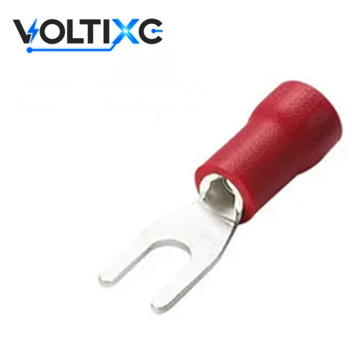
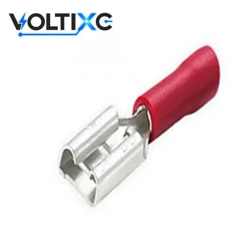
Pick a fork when the screw has to stay in its hole during fitting or the wire comes off for service; pick a ring where a loose screw must not release the wire.
| Problem | What to do | Check |
|---|---|---|
| The screw is captive, or backing it fully out is awkward | Fit a fork. The ABB Sta-Kon fork catalogue notes that fork terminals can be installed without completely removing the mounting screw | The fork slides under the loosened head while the screw stays in its thread |
| The wire comes off for testing or service | Use a fork and loosen the screw instead of removing it | The fork goes out and back without the screw leaving the hole |
| A loosened screw must not let the wire drop | Choose a ring. Wiltronics describes a ring as the pick where the fastener passes through it, so the connection cannot be removed without loosening or removing the fastener | The fastener passes through the closed eye |
| The terminal lands on a free-standing stud | Consider a wide-tongue fork; according to 3M, fork terminals have wider tongues that make them suited to free-standing studs | The tongue sits flat under the nut and washer |
| A locking fork is offered in place of a ring | Judge it as a fork: its hold depends on the tongue design, the hardware and the vibration duty | The equipment maker’s instructions allow a fork at that point |
| The joint sees high-vibration service, as in automotive wiring or on industrial equipment | Fit a ring unless the equipment maker allows a fork at that point | The maker’s instructions name the terminal type |
| The wire stays on for good and never comes off for service | Use a ring; quick removal brings nothing to permanent connections | The ring sits on the stud under the nut |
| Either electrical terminal, a ring or a fork, would fit | Size either one to the stud; for rings, the ring terminal lookup tool looks up the listed RV and RNY series by wire size and insulation | Terminal opening and stud share one nominal size |
This guide gives no vibration rating for a fork or a ring. Where the equipment maker or an installation code names the terminal type, follow it. For the ring side of the choice, VoltixC lists vinyl and nylon series on its ring terminals page.
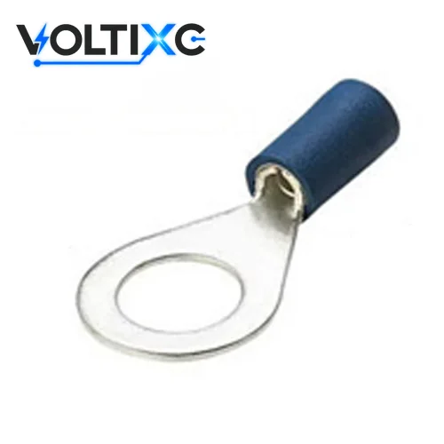
A standard fork is the default for screw terminals; the flanged, locking, block and hook shapes each solve one fitting problem, listed in the table.
Burndy‘s fork tongue range includes PVC-insulated, nylon-insulated, uninsulated and heat-shrink insulated versions, plus locking, block and flanged fork shapes.
| Tongue style | Shape | Where it fits | What to check | VoltixC listing |
|---|---|---|---|---|
| Standard fork | Two straight prongs with an open end | The default for screw terminals and studs with room to slide the fork in; start here unless a drawing or terminal-block maker names another tongue | Fork opening against the stud size | VoltixC lists SV vinyl and SNY nylon series on the SV and SNY spade terminal page |
| Flanged fork | Prong tips turned up so the fork resists sliding out | Screws that may back off a little in service | The tips clear the screw head when tightened | Not on the current list; ask before you specify (new tooling, confirmed per order) |
| Locking fork | Prongs shaped to snap around the screw shank | Points where the fork must stay in place while the screw is loose | It clicks on and needs a deliberate pull to come off | Not on the current list; ask before you specify (new tooling, confirmed per order) |
| Block fork | Tongue cut to the pocket of a specific terminal block | Terminal blocks whose maker names this tongue | The tongue drops into the pocket without trimming | Not on the current list; ask before you specify (new tooling, confirmed per order) |
| Hook | A single curved prong in place of two | Terminal strips whose maker names a hook | The hook sits fully under the screw head | Not on the current list; ask before you specify (new tooling, confirmed per order) |
Vinyl suits dry panel wiring; step up to nylon when the wire will flex, or to heat shrink in wet spots.
On the VoltixC list, SV forks carry PVC (vinyl) sleeves and SNY forks nylon, both over a tin-plated copper body per supplier specification sheet; SNY crimp construction is confirmed per order. Bare and heat-shrink forks are not on the current list; ask before you specify. Neither sleeve gets a temperature figure here, so take that from the maker’s data sheet. The heat-shrink crimp terminals page explains how sealed sleeves go on.
| Point | What the data says | Source |
|---|---|---|
| Vinyl (PVC), as on SV forks: cost and protection | Vinyl insulation is the most economical option and gives basic protection against accidental contact | Waytek |
| Vinyl (PVC), as on SV forks: strain relief | Vinyl-insulated terminals give less strain relief than nylon or heat-shrink insulated terminals | Waytek |
| Nylon, as on SNY forks (crimp construction confirmed per order): double crimp | Many nylon-insulated terminals are designed for double crimping, which adds strain relief and tensile strength | Waytek |
| Heat-shrink seal | Heat-shrink insulated terminals seal tightly when heated properly, giving moisture resistance and corrosion protection | Waytek |
| Vinyl sleeve length | Its vinyl-insulated fork terminals use an extra-long PVC insulation sleeve for protection and stress relief at the wire flex point | ABB |
| Barrel metal | Its fork terminals are high-conductivity electrolytic copper, electro-tin plated, with a serrated brazed-seam barrel for pull-out resistance | ABB fork terminal catalogue |
| Insulation support | PIDG terminals combine a nylon or PVC-insulated body with a metal sleeve that crimps onto the wire insulation for support | TE Connectivity, PIDG |
| Bending at the joint | The copper insulation-support sleeve lets the wire bend in any direction without fraying the insulation or breaking the conductor | TE Connectivity, PIDG page |
| Two barrels, two jobs | The wire barrel provides the electrical and mechanical connection, while the insulation barrel provides strain relief and requires a more relaxed crimp without providing an electrical connection | TE Connectivity, Guide to Crimping |
Source: Waytek, the ABB fork terminal catalogue and TE Connectivity (PIDG page and Guide to Crimping); each row describes that maker’s own parts, not VoltixC parts.
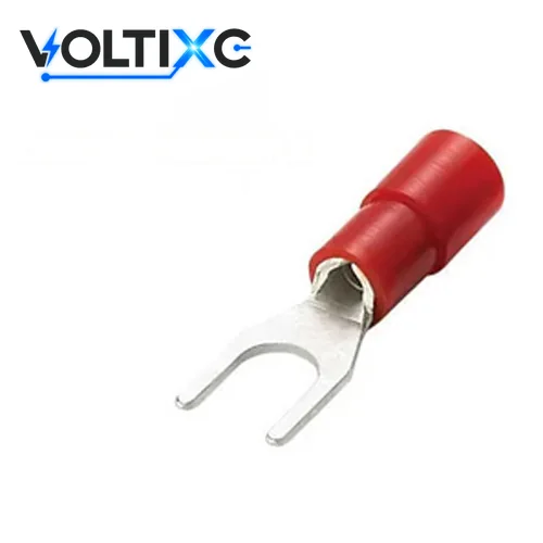
Pick the wire band that contains your conductor gauge, then match the fork opening to the stud or screw; sleeve colour hints at the band but differs between makers.
| Input | Where to read it | What it decides |
|---|---|---|
| Conductor size (AWG or mm²) | Printed on the wire jacket or in the wire specification | The wire band printed on the terminal |
| Insulation outside diameter | A caliper on the jacket | Whether the sleeve entry takes the wire; ABB, for one, sells fork terminals with an ‘X’ suffix that have a wider wire entry to accommodate heavy-wall insulation |
| Stud or screw size | The equipment drawing, or the screw itself (a #10 screw, an M5 stud) | The fork opening |
| Stud rule on boats | West Marine writes that ring and captive-spade terminal connectors should be the same nominal size as the stud under ABYC E-11.14.4.1.11 | A fork one size too big for the stud is out |
| Sleeve colour | The maker’s own chart | A quick band check; ABB’s Spec-Kon guide says insulated terminals use colour-coded insulators according to DIN cable sizes |
The sizing rule has two parts. The printed wire band must include the conductor gauge, and the fork opening must equal the stud’s nominal size. Colour codes are only a first check. Waytek’s code runs red 22–18, blue 16–14 and yellow 12–10 AWG. VoltixC lists its smallest band as 22–16 AWG.
| AWG wire band | mm² | SV vinyl: sleeve colour, part numbers | SNY nylon: die colour, part numbers | Studs listed (stud hole Ø d2, mm) |
|---|---|---|---|---|
| 22–16 | 0.5–1.5 | Red, 11 part numbers | Red, 22 part numbers | #4 (3.2), #6 (3.7), #8 (4.3), #10 (5.3), 1/4 in (6.4) |
| 16–14 | 1.5–2.5 | Blue, 11 part numbers | Blue, 22 part numbers | #4 (3.2), #6 (3.7), #8 (4.3), #10 (5.3), 1/4 in (6.4) |
| 14–12 | 2.5–4 | Black, 4 part numbers | Not on the current list; ask before you specify | #6 (3.7), #8 (4.3), #10 (5.3), 1/4 in (6.4) |
| 12–10 | 4–6 | Yellow, 9 part numbers | Yellow, 18 part numbers | #6 (3.7), #8 (4.3), #10 (5.3), 1/4 in (6.4), 5/16 in (8.4) |
| 8 AWG and larger | — | Not on the current list; ask before you specify | Not on the current list; ask before you specify | — |
Source: per supplier specification sheet (SV and SNY series), the basis of this spade terminal size chart; not individually re-tested; 97 part numbers in the full specification table — request the complete list with your quote.
Worked example: A 14 AWG stranded wire going to a #10 screw sits in the 16–14 AWG band, which VoltixC lists in both SV vinyl and SNY nylon. On Waytek’s chart that band is blue. The #10 fork in that band, such as SVS2-5 or SNYS2-5, has a 5.3 mm stud hole d2 on the supplier sheet.
The SV and SNY supplier sheets list studs from #4 to 5/16 in, each with its stud hole d2; a metric stud such as M5 is not on the current list, so ask before you specify. This guide gives no current rating for a fork terminal; fork terminal sizes here mean the wire band and the stud only.
Strip the wire to the barrel length, insert it fully, crimp it with a tool made for insulated terminals, pull-test the joint, then clamp the fork under the screw and tighten to the equipment maker’s torque.
Strip the insulation to the length of the fork’s wire barrel.
Laid beside the terminal, the bare end reaches the far end of the barrel and every strand is whole.
Push the conductor into the barrel until the insulation meets the sleeve entry.
If a strand folds back at the entry, pull the wire out, twist the strands lightly and insert it again.
Close the crimp tool through its full stroke in the die nest marked for the terminal’s wire band.
Look for an indent centred on the wire barrel and a sleeve with no crack.
Hold the terminal and pull the wire straight and steadily by hand.
Nothing moves; a fork that shifts is cut off and replaced.
Slide the fork under the loosened screw head or stud nut and tighten it to the torque the equipment maker gives.
The tongue lies flat, both prongs sit under the head, and no bare copper shows behind the sleeve.
| Step | What the source says | Source |
|---|---|---|
| Before you start | A quality crimp requires correct tooling for the terminal and wire, the correct terminal for the application, properly prepared wire, and a trained operator | TE Connectivity, Guide to Crimping |
| Strip | Insulation must be removed to the proper length cleanly, without nicking or breaking wire strands; the manual illustrates acceptable and rejected strip examples | TE Connectivity, Guide to Crimping |
| Strip | Strip enough insulation for the conductor to fill the terminal’s wire barrel without leaving unnecessary bare wire exposed behind the connector | Wiltronics |
| Insert | A funnelled wire entry prevents turned-back strands and speeds wire insertion | TE Connectivity, PIDG |
| Insert | Insulation outside diameters vary among wires with the same AWG size, so the insulation barrel must accommodate the wire’s outside diameter and the crimp range must match it | TE Connectivity, Guide to Crimping |
| Crimp | Ordinary pliers should not be used on standard pre-insulated butt, ring, fork or spade terminals unless the maker states they are suitable | Wiltronics |
| Pull test | A crimp that moves or pulls out in a steady in-line pull test should be cut off and redone with a new terminal, and crimped terminals should not be reused | Wiltronics |
We give no torque figure; the equipment or terminal-block maker sets it. For push-on parts, how to connect spade connectors is the same first four steps, and then the receptacle goes fully onto its tab. Die nests and pull checks for every terminal family are in the how to crimp wires guide.
Tip: Before a batch, crimp one fork onto a scrap of the same wire, pull it, and keep the die nest that passed.
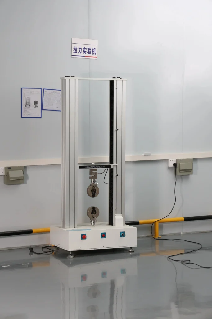
Replace a fork that does not fit its wire or stud; a wrong size makes a joint run hot or slip out.
| Problem | What to do | Check |
|---|---|---|
| The fork runs warm or darkens at the tongue | Recheck the wire band against the gauge and the fork opening against the stud; replace the terminal if either is wrong | The band covers the gauge and the tongue sits flat under the screw |
| The wire pulls out of the barrel | Cut the terminal off and crimp a new one. Wiltronics says a crimp that moves or pulls out in a steady in-line pull test should be cut off and redone with a new terminal, and crimped terminals should not be reused | The new crimp passes a straight hand pull |
| The fork slips out from under the screw | Match the opening to the stud, then retighten to the equipment maker’s torque | The screw head covers both prongs |
| Vibration keeps loosening the joint | Change to a ring terminal where the equipment maker allows it | No loosening at the next inspection |
| Green or white corrosion on the tongue in a damp spot | Replace it with a sealed part; heat-shrink insulated terminals seal tightly when heated properly, giving moisture resistance and corrosion protection, per Waytek | The shrunk sleeve grips the jacket with no gap |
| The sleeve is cracked or cut | Crimp a new terminal in the insulated-terminal die nest | The new sleeve is whole |
| A heat-shrink sleeve was left loose | Apply heat with a heat gun as the terminal maker directs | The sleeve grips the jacket with no gap |
| The wire is too small for the circuit | Move up to the wire gauge the wiring project calls for, and to the band that covers it | The new wire and the band on the terminal agree |
| Bare copper shows behind the sleeve | Strip shorter and fit a new fork | No copper is visible between sleeve and jacket |
A pull-out points to a weak crimp and green deposits to damp; the table gives each fix. A loose terminal-block screw can make a joint run warm too, so put a screwdriver on it before you cut the fork off. Aluminium wire and mixed metals aren’t covered here; ask before you specify.
Caution: A fork that failed the pull test does not get a second squeeze. Cut it off, strip fresh wire and crimp a new terminal.

VoltixC lists 97 fork part numbers in two series, SV vinyl and SNY nylon, on the spade terminals page; push-on blades sit on the quick disconnect range page.
| Part | VoltixC series | Wire bands listed | Where to go |
|---|---|---|---|
| Vinyl-insulated fork | SV (35 part numbers) | 22–16, 16–14, 14–12 and 12–10 AWG | SV vinyl forks |
| Nylon-insulated fork | SNY (62 part numbers, 31 butted / brazed seam pairs) | 22–16, 16–14 and 12–10 AWG | SNY nylon forks |
| Non-insulated, heat-shrink, flanged, locking, block or hook fork | — | Not on the current list; ask before you specify | Quote request |
| Male and female push-on blades | Six vinyl and nylon series, 52 part numbers | 22–16, 16–14 and 12–10 AWG | push-on terminal page |
| Ring terminals | Vinyl and nylon series | See the product page | RV and RNY ring terminals |
| Round pin-and-socket parts | Vinyl series | See the product page | FRD and MPD bullet terminals |
Source: per supplier specification sheet (SV, SNY and quick disconnect series); not individually re-tested; 97 spade part numbers in the full specification table — request the complete list with your quote.
For a quote, send the stud or screw size, the wire gauge and a photo of the mating hardware; those three items identify the fork or push-on family, and the part number follows from the listed stud sizes. VoltixC offers fastest sampling from 7 days, confirmed per order. Sizing tables for female push-on receptacles are in the receptacle sizing guide. All of these parts sit in the VoltixC crimp connectors range.
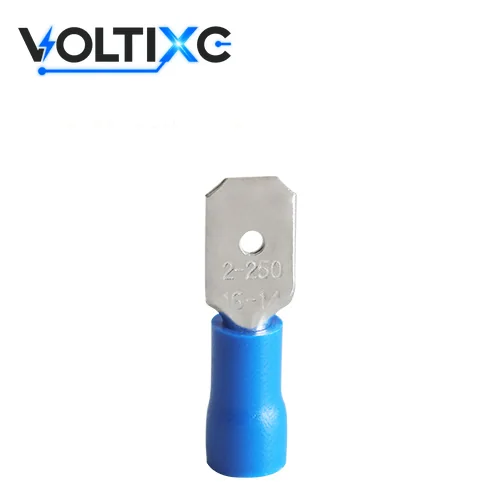
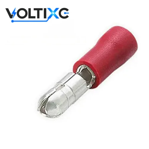
The word covers a fork that slips under a screw and a blade that pushes into a receptacle. An order for “spade connectors” by gauge alone can bring back either part. Write fork or push-on blade on the order, and add the stud size or the tab width.
When the screw is hard to take out, or when the wire comes off for service. ABB’s Sta-Kon catalogue notes that fork terminals can be installed without completely removing the mounting screw.
No. A locking fork’s hold depends on its tongue design, the screw hardware and the vibration the joint sees. A ring stays on because the fastener passes through it, so the connection cannot be removed without loosening or removing the fastener, as Wiltronics puts it. Where the equipment maker names a ring, fit a ring.
Match the conductor gauge to the printed wire band first, then set the fork opening to the stud. Measure the insulation too: TE Connectivity points out that insulation outside diameters vary among wires with the same AWG size, so the insulation barrel must accommodate the wire’s outside diameter. VoltixC lists its SV and SNY forks for studs from #4 to 5/16 in.
A second grip, on the wire insulation. Waytek’s Terminals 101 article says many nylon-insulated terminals are designed for double crimping, which adds strain relief and tensile strength. In TE Connectivity’s PIDG design, the copper insulation-support sleeve lets the wire bend in any direction without fraying the insulation or breaking the conductor. The wire barrel still carries the current; the second crimp only holds the jacket.
With the quick disconnect range, kept apart from the screw-mounted forks. UL 310 applies to quick-connect terminals, both connectors and tabs, with nominal widths of 2.8, 3.2, 4.8, 5.2 and 6.3 mm (0.110, 0.125, 0.187, 0.205 and 0.250 in). Receptacle sizing is in the female receptacle sizing guide.
They do different jobs, so the connection point decides. A fork clamps a wire under a screw or stud, while a bullet connector joins two wires in line with a round pin and socket that pull apart by hand. Use a fork at a screw terminal and a bullet where an in-line wire needs a quick disconnect; the bullet connector crimping guide covers the second case.
How this guide was written: the sources are ABB (Thomas & Betts Sta-Kon and Spec-Kon), 3M, Burndy, UL Standards & Engagement (UL 310), TE Connectivity, West Marine, Waytek and Wiltronics. Naming a standard here is not a claim that a VoltixC part is certified to it. VoltixC ran no tests for this guide, so it gives no current, temperature, torque or pull-force values of its own. Wire bands, studs, stud holes and colours for the SV and SNY series, and the quick disconnect wire bands, come from supplier specification sheets and have not each been re-tested.
VoltixC is the brand of Guangzhou FuTeXin Technology Co., Ltd. It makes the SV and SNY fork terminals and the push-on blades this guide describes, and it does not make or sell crimp tools.