VOLTIXC / ENQUIRY
Request a Quote
Tell us what you need and we will review your enquiry.

Female, male and flag crimp disconnects in vinyl and nylon sleeves, 22-16 to 12-10 AWG
Fast answer: Quick disconnect terminals are crimp terminals with a flat tab (male) and a matching receptacle (female) that push together and pull apart. VoltixC lists six series here, four female and two male, in 22-16, 16-14 and 12-10 AWG bands. Choose gender, tab width, wire gauge and insulation, then request a quotation.
The range covers 52 part numbers on the supplier specification sheets: a straight female receptacle with a vinyl barrel sleeve, fully insulated female receptacles in vinyl or nylon, a nylon flag receptacle for right-angle wire exits, and male tabs in vinyl or fully insulated nylon. Each part number takes one wire band and one tab size, from a 2.8 mm to a 9.4 mm tab. The page sits in the VoltixC crimp connector range.
| Figure | What it covers |
|---|---|
| 6 series | 4 female (FDD, FDFD, FDFN, FLDNY) and 2 male (MDD, MDFN) |
| 52 part numbers | 40 female and 12 male, per supplier specification sheet |
| 22-16 to 12-10 AWG | 0.5-1.5, 1.5-2.5 and 4-6 mm² in three bands |
| Tin-plated copper or brass body | Copper for FDD, brass for the other five series; PVC (vinyl) or nylon sleeve |
Quick disconnect terminals join a crimped wire to a flat tab through a spring receptacle, so the joint opens by hand and closes again without tools. According to Burndy, a female quick disconnect has a receptacle front end that slides onto and off a male blade. Quick disconnect connectors, blade connectors, electrical quick connect terminals and wiring quick connects all name these parts, and a female spade connector plus a male spade connector make up one joint.
Current passes through four points in order:
The wire barrel, crimped onto the conductor, carries current from the wire into the terminal.
The insulation sleeve grips the wire jacket and takes bending load off the crimp.
The receptacle’s rolled sides press on both faces of the tab; that contact force is the electrical path between the two halves.
A detent locks the halves in position. According to Burndy, the dimpled detent in its female socket gives a firm grip on the tab.
The weak point is the sliding contact in step 3. Research on low-force electrical contacts identifies fretting corrosion, the wear and oxidation left by micro-motion between two touching surfaces, as a typical problem. For tin-plated contacts, published work lists fretting amplitude, frequency, temperature, humidity, normal load and current load as the conditions that shape it. One study of tin-plated tab connectors counted a joint as failed once its contact resistance reached ten times the starting value.
What that means for a buyer: a tab thinner than the receptacle was formed for bends the spring sides less, so contact force can drop and the joint moves more under vibration. That is why the selection table further down starts with the mating tab, and only then turns to the wire gauge.
Six series hold 52 quick disconnect terminals on the supplier specification sheets: 40 female and 12 male part numbers across the 22-16, 16-14 and 12-10 AWG bands. Each part number pairs one wire band with one tab size, so the two tables below give one row per band and tab width, and a thinner-tab version of the same size sits in the last column.
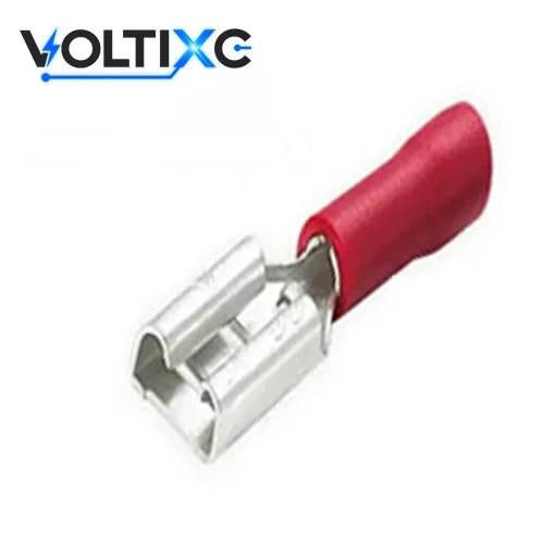
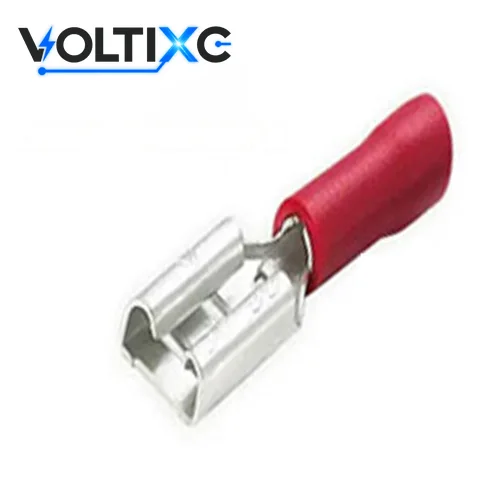
FDD is the straight female receptacle with a vinyl sleeve over the barrel only, so the metal mouth of the receptacle stays visible, unlike the fully insulated FDFD and FDFN families. It is also the one series with a copper body; the other five are brass.
Photo: an FDD sample with a red vinyl sleeve and the metal receptacle mouth in view; red is the 22-16 AWG colour on the sheet.
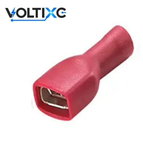
FDFD keeps the vinyl sleeve but carries it over the receptacle body as well as the barrel; the mating fit still depends on the male tab’s width and thickness.
Photo: an FDFD sample in a red vinyl body that covers the receptacle.
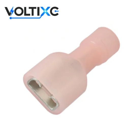
FDFN has the same fully insulated female form as FDFD, with a nylon sleeve in place of vinyl. Its sheet prints a temperature figure of 105, against 75 for the vinyl series, with no unit and no flame rating.
Photo: an FDFN sample in a translucent nylon body.
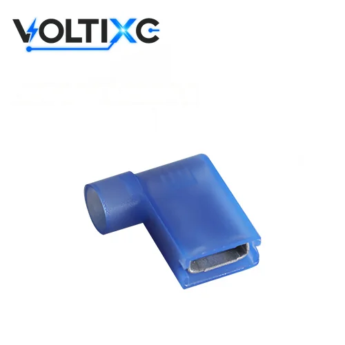
FLDNY is the one family of flag terminals on this page: the wire leaves at a right angle to the tab, for layouts with little room in front of the tab. Its three part numbers, FLDNY1.25-250, FLDNY2-250 and FLDNY5.5-250, all take a 6.35 mm tab.
Photo: an FLDNY sample with a blue nylon sleeve.
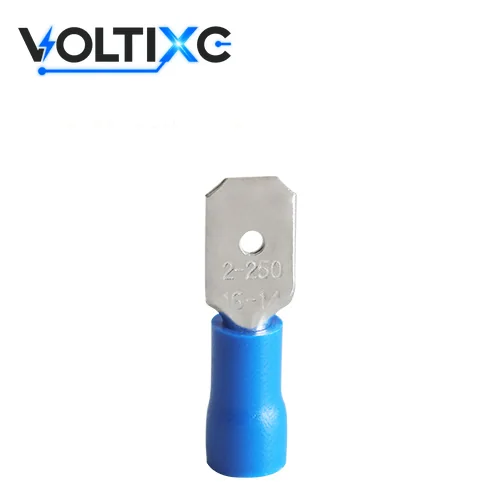
MDD is the male tab with a vinyl sleeve over the barrel. It pairs with any female family above once tab width and thickness match.
Photo: an MDD sample with a blue vinyl sleeve.
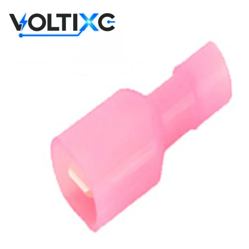
MDFN puts a fully insulated nylon sleeve on the male side; how far the shroud reaches along the tab is confirmed per order.
Photo: an MDFN sample in a translucent nylon shroud.
| Part No. | Wire (AWG) | mm² | Mating tab width (mm) | Mating tab thickness (mm) | Length L (mm) | Insulation color | Temp. rating (no unit printed) | Also listed (same band and tab width) |
|---|---|---|---|---|---|---|---|---|
| FDD1.25-110(8) | 22-16 | 0.5-1.5 | 2.8 | 0.8 | 19 | Red | 75 | FDD1.25-110(5) (0.5 mm thick tab) |
| FDD1.25-187(8) | 22-16 | 0.5-1.5 | 4.75 | 0.8 | 19.4 | Red | 75 | FDD1.25-187(5) (0.5 mm thick tab) |
| FDD1.25-205(8) | 22-16 | 0.5-1.5 | 5.2 | 0.8 | 19.3 | Red | 75 | FDD1.25-205(5) (0.5 mm thick tab) |
| FDD1.25-250 | 22-16 | 0.5-1.5 | 6.35 | 0.8 | 20.8 | Red | 75 | — |
| FDD1.25-312 | 22-16 | 0.5-1.5 | 8.0 | 0.8 | 24.5 | Red | 75 | — |
| FDD2-110(8) | 16-14 | 1.5-2.5 | 2.8 | 0.8 | 19 | Blue | 75 | FDD2-110(5) (0.5 mm thick tab) |
| FDD2-187(8) | 16-14 | 1.5-2.5 | 4.75 | 0.8 | 19.4 | Blue | 75 | FDD2-187(5) (0.5 mm thick tab) |
| FDD2-205(8) | 16-14 | 1.5-2.5 | 5.2 | 0.8 | 19.3 | Blue | 75 | FDD2-205(5) (0.5 mm thick tab) |
| FDD2-250 | 16-14 | 1.5-2.5 | 6.35 | 0.8 | 20.8 | Blue | 75 | — |
| FDD2-312 | 16-14 | 1.5-2.5 | 8.0 | 0.8 | 24.5 | Blue | 75 | — |
| FDD2-375 | 16-14 | 1.5-2.5 | 9.4 | 1.2 | 26.1 | Blue | 75 | — |
| FDD5.5-110(8) | 12-10 | 4-6 | 2.8 | 0.8 | 22 | Yellow | 75 | FDD5.5-110(5) (0.5 mm thick tab) |
| FDD5.5-187(8) | 12-10 | 4-6 | 4.75 | 0.8 | 22 | Yellow | 75 | FDD5.5-187(5) (0.5 mm thick tab) |
| FDD5.5-250 | 12-10 | 4-6 | 6.35 | 0.8 | 23.3 | Yellow | 75 | — |
| FDD5.5-375 | 12-10 | 4-6 | 9.4 | 1.2 | 28.6 | Yellow | 75 | — |
| FDFD1.25-110(8) | 22-16 | 0.5-1.5 | 2.8 | 0.8 | 18.9 | Red | 75 | FDFD1.25-110(5) (0.5 mm thick tab) |
| FDFD1.25-187(8) | 22-16 | 0.5-1.5 | 4.75 | 0.8 | 19.5 | Red | 75 | FDFD1.25-187(5) (0.5 mm thick tab) |
| FDFD1.25-250(5) | 22-16 | 0.5-1.5 | 6.35 | 0.8 | 22.5 | Red | 75 | — |
| FDFD2-110(8) | 16-14 | 1.5-2.5 | 2.8 | 0.8 | 19.6 | Blue | 75 | FDFD2-110(5) (0.5 mm thick tab) |
| FDFD2-187(8) | 16-14 | 1.5-2.5 | 4.75 | 0.8 | 20.5 | Blue | 75 | FDFD2-187(5) (0.5 mm thick tab) |
| FDFD2-250 | 16-14 | 1.5-2.5 | 6.35 | 0.8 | 23.6 | Blue | 75 | — |
| FDFD5.5-250 | 12-10 | 4-6 | 6.35 | 0.8 | 24.2 | Yellow | 75 | — |
| FDFN1.25 | 22-16 | 0.5-1.5 | 6.35 | 0.8 | 22 | Red | 105 | — |
| FDFN2 | 16-14 | 1.5-2.5 | 6.35 | 0.8 | 22 | Blue | 105 | — |
| FDFN5.5 | 12-10 | 4-6 | 6.35 | 0.8 | 24 | Yellow | 105 | — |
| FLDNY1.25-250 | 22-16 | 0.5-1.5 | 6.35 | 0.8 | 16 | Red | 105 | — |
| FLDNY2-250 | 16-14 | 1.5-2.5 | 6.35 | 0.8 | 16 | Blue | 105 | — |
| FLDNY5.5-250 | 12-10 | 4-6 | 6.35 | 0.8 | 16.5 | Yellow | 105 | — |
| Part No. | Wire (AWG) | mm² | Tab width (mm) | Tab thickness (mm) | Length L (mm) | Insulation color | Temp. rating (no unit printed) | Also listed (same band and tab width) |
|---|---|---|---|---|---|---|---|---|
| MDD1.25-110(8) | 22-16 | 0.5-1.5 | 2.8 | 0.8 | 19.2 | Red | 75 | MDD1.25-110(5) (0.5 mm thick tab) |
| MDD1.25-187(8) | 22-16 | 0.5-1.5 | 4.75 | 0.8 | 19.8 | Red | 75 | MDD1.25-187(5) (0.5 mm thick tab) |
| MDD1.25-250 | 22-16 | 0.5-1.5 | 6.35 | 0.8 | 21.8 | Red | 75 | — |
| MDD2-187(8) | 16-14 | 1.5-2.5 | 4.75 | 0.8 | 19.8 | Blue | 75 | MDD2-187(5) (0.5 mm thick tab) |
| MDD2-250 | 16-14 | 1.5-2.5 | 6.35 | 0.8 | 21.8 | Blue | 75 | — |
| MDD5.5-250 | 12-10 | 4-6 | 6.35 | 0.8 | 24 | Yellow | 75 | — |
| MDFN1.25 | 22-16 | 0.5-1.5 | 6.35 | 0.8 | 24 | Red | 105 | — |
| MDFN2 | 16-14 | 1.5-2.5 | 6.35 | 0.8 | 24 | Blue | 105 | — |
| MDFN5.5 | 12-10 | 4-6 | 6.35 | 0.8 | 25 | Yellow | 105 | — |
Source: VoltixC supplier specification sheets; values as printed, not re-tested by VoltixC.
Data note: 52 part numbers in the full specification table, all shown above; request the complete sheets with your quote. Tab sizes come from the sheets’ matching plug size column, the temperature figure is printed as 75 or 105 without a unit, and barrel and sleeve dimensions not shown here are on the sheets.
| Also searched as | What it is on this page | Series |
|---|---|---|
| female spade terminal, female spade electrical connectors, insulated female spade connectors, push on electrical connectors, slide connectors | The receptacle, the female half crimped onto the wire | FDD, FDFD, FDFN, FLDNY |
| male blade connector, blade terminal connectors, blade electrical connectors | The tab, the male half | MDD, MDFN |
| flag connector, flag electrical connectors, 90 degree female spade connector | A receptacle whose wire leaves at 90° to the tab | FLDNY |
| quick disconnect electrical connector, quick connect electrical connectors, push on connectors wiring, wire disconnects, stake ons | Any tab-and-receptacle pair on this page | All six series |
| 2.8mm spade connector, 2.8 mm spade connector | A receptacle or tab for the 2.8 mm tab | FDD, FDFD and MDD parts ending in -110 |
| female to female spade connector, piggyback electrical connectors | An adapter with two receptacles, or a receptacle with a second tab on its back | Not on the current list; ask before you specify |
Start from the part already fixed to the device, because it decides the gender and the tab size; the wire band and the sleeve come after. If the device carries a male tab, you need a female quick disconnect terminal from FDD, FDFD, FDFN or FLDNY. If the harness side must carry the tab, MDD or MDFN is the match.
| Check | What decides it | Where the answer sits |
|---|---|---|
| Gender | The half already on the device | Female: FDD, FDFD, FDFN, FLDNY; male: MDD, MDFN |
| Tab width and thickness | The mating tab, measured or taken from its drawing | Tab columns of the model tables: 2.8 to 9.4 mm wide, 0.5 to 1.2 mm thick |
| Wire band | Conductor size of your wire | 22-16, 16-14 or 12-10 AWG (0.5-1.5, 1.5-2.5 or 4-6 mm²) in the model tables |
| Wire jacket diameter | Outside diameter of the insulated wire | Send the wire spec or the measured diameter |
| Sleeve coverage | Whether metal may stay exposed after mating | Barrel sleeve: FDD, MDD; full sleeve: FDFD, FDFN, MDFN |
| Wire exit | Room in front of the tab | Straight: FDD, FDFD, FDFN; right angle: FLDNY |
| Sleeve material and temperature | Vinyl or nylon, per your drawing | Vinyl series print 75, nylon series 105 (no unit on the sheets) |
| Where the joint sits | An industrial panel, an appliance or other equipment design with a tab already fitted | This range fits; OEM automotive wire harness terminal systems are outside it, so ask before you specify |
| Operating environment | Vibration, moisture or salt spray at the joint, as in marine use | Name it in the enquiry; the sheets give no sealing or vibration data |
The second table shows the tab widths, in mm, that each series lists for a wire band, so you can go from a gauge and a tab straight to a series.
| Wire band (AWG) | FDD | FDFD | FDFN | FLDNY | MDD | MDFN |
|---|---|---|---|---|---|---|
| 22-16 (0.5-1.5 mm²) | 2.8, 4.75, 5.2, 6.35, 8.0 | 2.8, 4.75, 6.35 | 6.35 | 6.35 | 2.8, 4.75, 6.35 | 6.35 |
| 16-14 (1.5-2.5 mm²) | 2.8, 4.75, 5.2, 6.35, 8.0, 9.4 | 2.8, 4.75, 6.35 | 6.35 | 6.35 | 4.75, 6.35 | 6.35 |
| 12-10 (4-6 mm²) | 2.8, 4.75, 6.35, 9.4 | 6.35 | 6.35 | 6.35 | 6.35 | 6.35 |
Three checks catch the fits that go wrong:
A wire gauge that sits on a band edge, such as 16 AWG, appears in both 22-16 and 16-14; pick by the jacket diameter as well as the gauge.
Two wires of the same gauge can carry different jackets. According to TE Connectivity, insulation outside diameters vary among wires with the same AWG size, so the insulation barrel must accept the wire’s outside diameter and the crimp range must match it.
A receptacle and a tab of the same nominal width can still differ in thickness; FDD, FDFD and MDD list 0.5 mm and 0.8 mm tab versions of several widths, so quote the thickness of the mating tab too.
Sleeve coverage changes how much metal stays exposed after mating, and the sleeve material changes the plastic; the supplier sheets name the material and print a temperature figure of 75 for vinyl and 105 for nylon, without a unit. On a barrel-sleeve part the insulation covers the crimp zone only. A fully insulated part carries the sleeve over the receptacle or the tab body as well; on the female side, FDFD and FDFN are the fully insulated female quick disconnects.
| Series | Gender | Body, plating | Sleeve material | Temp. figure (no unit) | Coverage, from the series name |
|---|---|---|---|---|---|
| FDD | Female | Copper, tin | Vinyl (PVC) | 75 | Barrel sleeve only (partially insulated), receptacle mouth open |
| FDFD | Female | Brass, tin | Vinyl (PVC) | 75 | Fully insulated |
| FDFN | Female | Brass, tin | Nylon | 105 | Fully insulated |
| FLDNY | Female, flag | Brass, tin | Nylon | 105 | Insulated; coverage confirmed per order |
| MDD | Male | Brass, tin | Vinyl (PVC) | 75 | Barrel sleeve only (partially insulated), tab open |
| MDFN | Male | Brass, tin | Nylon | 105 | Fully insulated |
Quick disconnect terminals are made around a short list of nominal tab widths, and on this page the part-number suffix names the tab: -110 parts take the 2.8 mm tab and -250 parts the 6.35 mm tab printed on the supplier sheets. UL 310 applies to quick-connect terminals, both connectors and tabs, with nominal widths of 2.8, 3.2, 4.8, 5.2 and 6.3 mm (0.110, 0.125, 0.187, 0.205 and 0.250 in). According to the IEC 61210 summary, that standard covers non-insulated flat quick-connect terminations with a male tab of 2.8, 4.8, 6.3 or 9.5 mm, with hole or dimple detents, and a mating female connector.
| Nominal width (in) | Nominal width (mm) | Named in |
|---|---|---|
| 0.110 | 2.8 | UL 310; IEC 61210 |
| 0.125 | 3.2 | UL 310 |
| 0.187 | 4.8 | UL 310; IEC 61210 |
| 0.205 | 5.2 | UL 310 |
| 0.250 | 6.3 | UL 310; IEC 61210 |
| — | 9.5 | IEC 61210 |
On the VoltixC sheets, each part-number suffix stands for one printed tab width.
| Part-number suffix | Tab width printed on the sheets (mm) | Series with this suffix |
|---|---|---|
| -110 | 2.8 | FDD, FDFD, MDD |
| -187 | 4.75 | FDD, FDFD, MDD |
| -205 | 5.2 | FDD |
| -250 | 6.35 | FDD, FDFD, FLDNY, MDD; FDFN and MDFN print 6.35 mm without the suffix |
| -312 | 8.0 | FDD |
| -375 | 9.4 | FDD |
Width is half of the match. According to Burndy’s QP-F data sheet, the NEMA tab sizes it lists include 0.11 × 0.02, 0.19 × 0.02 and 0.25 × 0.03 in (width × thickness), so the receptacle is formed for a width and a thickness together.
A standards note for anyone writing a specification: UL 486C does not apply to terminal wire connectors, flat quick-connect terminals or soldering lugs. For this product class the quick-connect reference is UL 310. Citing UL 310 or IEC 61210 here gives you the width vocabulary; it says nothing about how any VoltixC item was assessed.
Keep quick disconnects when the device already has a flat tab and the joint has to come apart for service; switch when the device offers a screw, a stud or no fixed connection point at all. A female spade connector that pushes onto a tab belongs on this page. A spade or fork that clamps under a screw head belongs with spade terminals, even though the two share part of their name.
| Route | How it attaches | Pick it when | Return to quick disconnect terminals when |
|---|---|---|---|
| Quick disconnect terminals (this page) | Push-on receptacle over a flat tab | The device has a tab and the joint is opened for service | — |
| insulated spade terminals | Fork or spade clamped under a screw | The device has a screw terminal or terminal strip | The device has a tab instead of a screw |
| insulated ring terminals | Closed ring over a stud or screw | The joint must stay captured if the screw backs off | Service calls for removal by hand |
| insulated bullet connectors | Round pin in a round socket, wire to wire | Two loose wire ends meet in line | One side is a flat tab on a component |
| butt splices | Permanent crimp splice | The joint never needs to come apart | The joint has to be opened later |
Vibration is one reason to leave the push-on route. According to published research on connector contacts, tin-plated contacts are highly susceptible to fretting corrosion, which limits their use in electrical connectors. If the joint sits on a frame that shakes and nobody needs to open it, a ring on a stud or a crimped splice takes the sliding contact out of the circuit.
Switching route changes the enquiry as well as the part. A spade or ring order is sized by the screw or stud, while a quick disconnect order is sized by the tab width, the tab thickness and the 22-16, 16-14 or 12-10 AWG band; a splice order needs both wire gauges instead.
Three builds are not offered in this range, even where the names overlap:
Use quick disconnect terminals where a copper wire meets a flat tab and the part behind that tab will be swapped or serviced later. Aluminum wire and anything heavier than the 12-10 AWG band rule them out, and a joint that shakes but never gets opened is better off without a sliding contact. The six cards sort cases by connector shape and the cited sources, and no customer installation sits behind them.
A switch, thermostat or relay with blade connectors on its body takes a female receptacle on the harness side. Check the component drawing for the blade width and thickness first. With open space in front of the blade, the straight receptacles FDD, FDFD and FDFN all fit.
A technician replacing a fan, heater element or control board pulls the old part off its tabs and pushes the new one on without cutting a wire. Go fully insulated if a hand could reach other live parts near the joint.
FLDNY suits a tight enclosure because its wire leaves at a right angle and runs flat along the panel. A straight receptacle there would push its wire into a lid or the part in front of the tab.
UL 310 applies to quick-connect terminals for one or two 26–10 AWG copper conductors; terminals for aluminum conductors are outside it. In the IEC 61210 summary the scope is copper conductors up to 6 mm² flexible or rigid stranded or up to 2.5 mm² rigid solid, with aluminium excluded and rated voltage limited to 1,000 V AC / 1,500 V DC. Put aluminum wire on a terminal made for aluminum.
If the joint sits on a vibrating frame and nobody will ever open it, crimp a splice or put a ring on a stud so there’s no sliding contact left to fret. Published research on tin-plated contacts ties fretting corrosion to six conditions (amplitude, frequency, temperature, humidity, normal load and current load).
12-10 AWG is the heaviest band in all six series. Put heavier wire on a lug, or on a ring terminal over a stud.
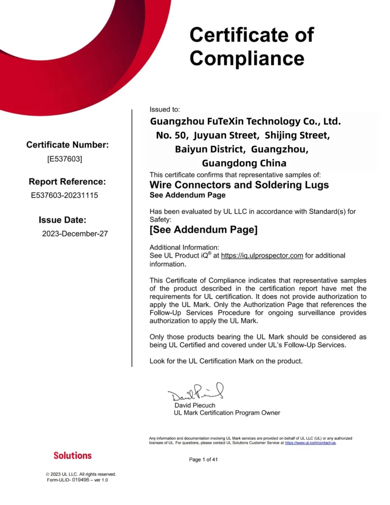
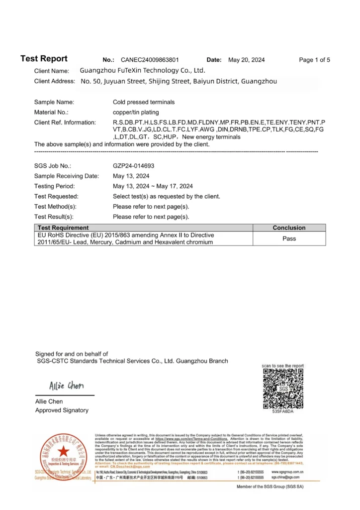
VoltixC is UL certified, holds a CE attestation under the Low Voltage Directive 2014/35/EU that covers the full terminal range, and has a RoHS test report available (SGS). The CE attestation cites EN 60947-7-1, EN 60947-7-2 and EN 60947-7-3, and all three documents name Guangzhou FuTeXin Technology Co., Ltd., the company behind the VoltixC brand. Certificate numbers and dates are not printed on this page.
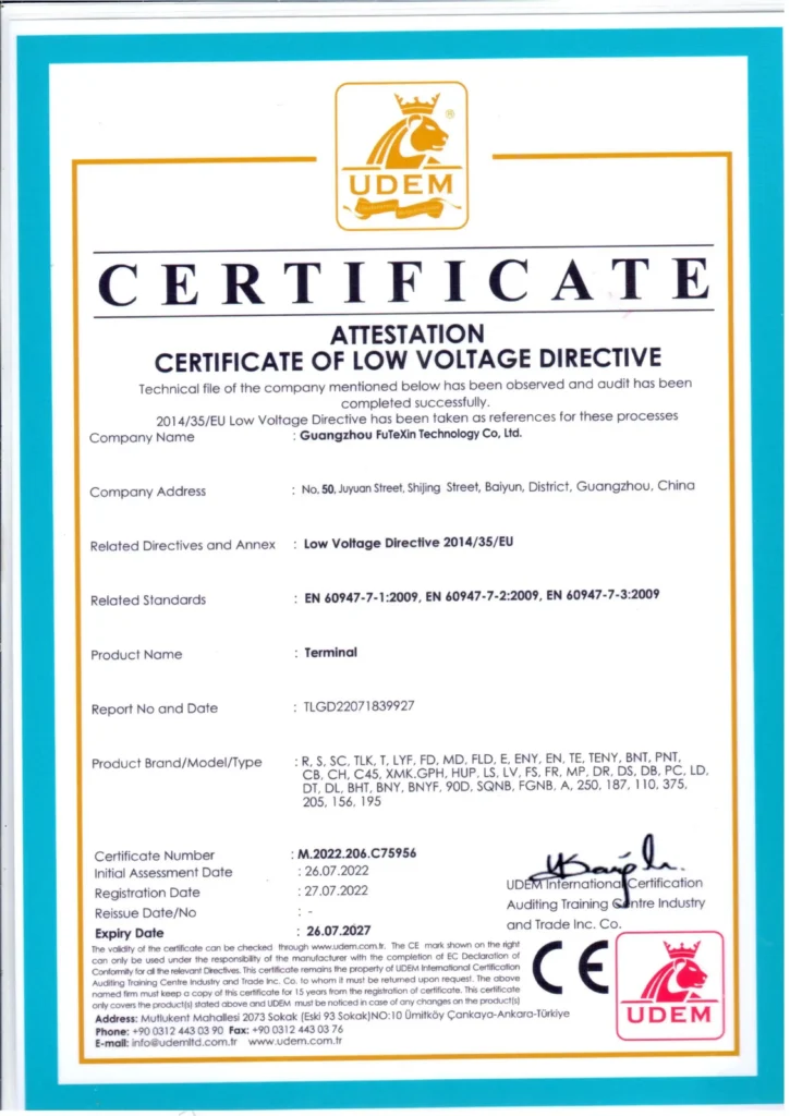
Before you approve a sample, request the documents and answers below along with the quote.
| Ask for | Why it matters on a quick disconnect |
|---|---|
| The UL addendum page for the series you order | The UL page shown here names no series or part numbers |
| The full specification sheet for your part numbers | It adds the barrel and sleeve dimensions the tables above leave out |
| The quick-connect standard the part is designed around | UL 310 is the quick-connect reference, and UL 486C excludes flat quick-connect terminals |
| A material declaration for vinyl sleeves if you ship to the EU | The SGS report covers four heavy metals; RoHS Annex II also sets phthalate limits, and PVC is the sleeve material to ask about |
| The pull-out strength the crimp was tested to | The supplier sheets print no pull-out or retention figure |
The factory photos show equipment on site. They do not state which machine handles which step of a quick disconnect order.




Seven choices move a quote for quick disconnect terminals: the item mix, the tab size, the sleeve, the finish, the colour, the packing and the documents your market asks for. Quantity sits on top of all seven. None of them has a published price attached, and each one is a decision you can make before the enquiry goes out.
| Driver | Effect on cost | What you control |
|---|---|---|
| Item mix across wire bands | Every extra item is its own production and packing line | Order only the bands you wire: 22-16, 16-14 or 12-10 AWG |
| Tab width and thickness | The sheets list tabs from 2.8 to 9.4 mm; a width outside that list can mean opening a die, confirmed per order | Measure the mating tab or send its drawing |
| Sleeve coverage and material | A full sleeve uses more plastic than a barrel sleeve; vinyl and nylon differ in raw material | Choose barrel or full sleeve by what must stay covered |
| Body finish | The sheets list tin plating on a copper (FDD) or brass body; nickel or silver plating is a custom request, confirmed per order | Say whether tin plating suits your mating tab |
| Sleeve colour | The sheets list red for 22-16, blue for 16-14 and yellow for 12-10 AWG; another colour is a special request, confirmed per order | List the colour you need for each item |
| Packing and labels | Loose bulk, counted packs and printed labels change handling time | Give the pack count and label text |
| Market documents | EU buyers of PVC sleeves ask about phthalates; under the amended RoHS Annex II, DEHP, BBP, DBP and DIBP are each limited to 0.1% by weight in homogeneous materials | Name the destination market |
| Quantity | A larger run spreads setup over more pieces | Give the per-shipment and yearly quantity |
MOQ, payment terms and lead time are confirmed per order by email or the enquiry form.
Samples let you try the push-on fit against your own tab before a production order; the shortest sampling time VoltixC gives is 7 days. The production schedule is agreed with the order.
Put these details in the enquiry:
Four pages on this site cover the sizing and crimping questions that come up before a quick disconnect enquiry.
Nominal tab widths, receptacle sizes and how to measure a tab are set out in the female spade connector sizes guide.
If the other end of the same wire lands on a stud, the ring terminal size chart matches stud and wire size.
Strip length, die choice and the pull check are in the how to crimp wires guide.
Tab, fork, ring, pin and splice shapes are compared in wire crimp connector types.
Yes. A female receptacle is formed for one tab width and one tab thickness, and the male tab must match both. According to Burndy’s QP-F data sheet, the NEMA tab sizes it lists include 0.11 × 0.02, 0.19 × 0.02 and 0.25 × 0.03 in (width × thickness). On this page the part-number suffix gives the width, such as 6.35 mm for -250, and the model tables give the thickness.
Two things differ. “Fully insulated” describes coverage: FDFD, FDFN and MDFN carry the sleeve over the receptacle or tab body, while FDD and MDD sleeve the barrel only. Vinyl and nylon are the sleeve materials. The supplier sheets print 75 for the vinyl series and 105 for the nylon series, with no unit and no voltage rating, so ask for the rating you need instead of reading it from the material name.
A flag terminal holds the receptacle at a right angle to the wire, so the wire runs along the panel when there is no room in front of the tab. The FLDNY series lists 3 flag part numbers, FLDNY1.25-250, FLDNY2-250 and FLDNY5.5-250, for 22-16, 16-14 and 12-10 AWG, all with a nylon sleeve and a 6.35 mm tab.
UL 310 names nominal quick-connect widths of 2.8, 3.2, 4.8, 5.2 and 6.3 mm (0.110, 0.125, 0.187, 0.205 and 0.250 in). On the supplier sheets for this page, receptacles take tabs of 2.8, 4.75, 5.2, 6.35, 8.0 and 9.4 mm, and the male parts come in 2.8, 4.75 and 6.35 mm.
Three bands: 22-16, 16-14 and 12-10 AWG, which the sheets give as 0.5-1.5, 1.5-2.5 and 4-6 mm². All six series cover all three bands, with 52 part numbers in total. Wires of the same gauge can differ in jacket diameter, and according to TE Connectivity the insulation barrel must accept the wire’s outside diameter.
Crimp the wire barrel first, then the insulation barrel, with the die the terminal maker specifies for insulated terminals. According to TE Connectivity, the wire barrel provides the electrical and mechanical connection, while the insulation barrel provides strain relief with a more relaxed crimp. The crimping guide covers strip length and the pull check.
A female spade connector, a female quick disconnect terminal or a receptacle are names for the same part; the male half is called a tab, a blade or a male spade connector. According to Burndy, the female part has a receptacle front end that slides onto and off the male blade.
One published scheme ties sleeve colour to conductor size. According to ABB’s Spec-Kon vinyl-insulated ring table, red denotes 0.5–1.5 mm², blue denotes 1.5–2.5 mm², and yellow denotes 4.0–6.0 mm² conductors. The supplier sheets for these six series use the same colours by band: red for 22-16 AWG, blue for 16-14 AWG and yellow for 12-10 AWG.
Not these. UL 310 requirements apply to quick-connect terminals for 26–10 AWG copper conductors and do not apply to terminals for aluminum conductors. Use a terminal made for aluminum instead.
The wire bands and part numbers are printed on the VoltixC supplier specification sheets and have not been re-tested item by item. One detail to confirm on the quote: the 12-10 AWG FDFD part appears as FDFD5.5-250 on its sheet but as FDFD5 in older listings.
Ask for a material declaration that covers phthalates. Under the amended RoHS Annex II, DEHP, BBP, DBP and DIBP are each limited to 0.1% by weight in homogeneous materials. VoltixC has a RoHS test report available (SGS), but it covers lead, mercury, cadmium and hexavalent chromium, not phthalates, so the declaration is a separate request.
Put the mating tab width and thickness, the AWG band, the sleeve type and the quantity in one message, and send it through the form or to hugo@voltixconnect.com. The form has no upload field, so tab drawings and photos go by email.
Ask a VoltixC Engineer