VOLTIXC / ENQUIRY
Request a Quote
Tell us what you need and we will review your enquiry.

Copper C-tap connector, TC4008 series, for branch and parallel joints on copper conductors
Fast answer: A C-tap connector is a C-shaped copper compression connector crimped around an electrical run conductor and a tap conductor to make a branch or parallel joint. VoltixC lists one model, the TC4008, with a copper body per supplier data. Send your run and tap sizes and the die your compression tool takes, and the fit is checked before the quote.
This page covers one series, TC4008, and one listed model. The supplier record gives the model number and a copper body; for everything else, the parameter table below sets typical C-tap values from published references beside what your order is built to.
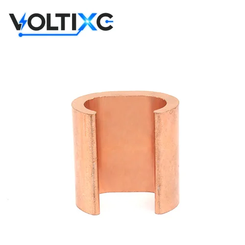
A C-tap connector joins a branch conductor to a run conductor without cutting the run. Its copper body is open on one side, like the letter C, so it can be hooked over a conductor that is already in place. According to Thomas & Betts installation instructions, a C-tap is placed over the main (run) conductor and the branch (tap) conductor is inserted before compression. A compression tool with a matching die then closes the body around both conductors.
C tap, copper C tap, C crimp connector, C-type compression connector and C tap compression connector all name this same part, one of several compression taps; below it is called a C-tap connector.
The joint is made in three stages:
Hook the open C over the run conductor at the tap point.
Lay the stripped tap conductor into the C beside the run conductor.
Close the body with the die so the copper grips both conductors.
According to the same Thomas & Betts instructions, C-tap connectors are made of high-conductivity copper and each C-tap covers a range of conductor sizes. So a C-tap is chosen by conductor pair, not by one size. Both the run size and the tap size must sit inside the range of a single part, and the die must be the one named for that part. A joint that misses either condition can loosen in service.
Two standards describe this class of connector. According to UL Standards & Engagement, UL 486A-486B applies to single-polarity connectors used with copper, aluminum or copper-clad aluminum conductors in installations governed by the Canadian Electrical Code, NFPA 70 or NOM-001-SEDE. For projects that follow IEC practice, IEC 61238-1-1 applies to compression and mechanical connectors for power cables up to 1 kV (Um = 1.2 kV) on non-insulated conductors. Both are cited to describe the connector class only, and the TC4008 is not claimed to be certified to either.
A C-tap connector is chosen by the conductor pair, the die and the cover, in that order. The TC4008 supplier record lists none of the three, so each one is settled from the details you send with the enquiry.
| Check | What decides it | What to send |
|---|---|---|
| Run conductor | The continuous conductor the tap leaves; its size must sit inside the part’s run range | Size in AWG, kcmil or mm², plus stranding (for example 2 AWG or 4 AWG) |
| Tap conductor | The branch conductor; its size must sit inside the part’s tap range | Size and stranding of the branch (for example 6 AWG) |
| Conductor metal | The TC4008 body is copper; supplier data gives no rating for other conductor metals | Copper, aluminum or copper-clad aluminum |
| Die and tool | The die named for the part, matched to the compression tool you own | Tool model and die family |
| Insulation cover | Whether the finished joint must be covered | Cover type and service conditions |
Die selection comes first in the field. According to the ILSCO installation guide, installers should select the compression die specified by the connector manufacturer, and colored bands, dots or stamped die codes may identify the die. Ask for the die reference with the quote, and check it against your tool before the parts ship.
Covers are a separate choice. According to Thomas & Betts, its C-tap instruction sheet lists shrink tubing and adhesive insulation choices for each C-tap size. If the joint will sit in a raceway, an enclosure or a wet location, name that location so the cover can be matched to the finished C-tap size.
Send one line per joint type with its run and tap pair, and each line is checked against a part.
Send My Size ListThe TC4008 supplier listing gives a model number and a copper body, so every other parameter below is shown as the typical value for C-tap connectors from published references, beside what your order is built to.
TC4008 is the only series and the only listed model on this page. The supplier lists it under the title “C Shape Copper Crimp Connector TC4008”.
| Parameter | Typical for C-tap connectors (published reference) | TC4008 |
|---|---|---|
| Body metal | High-conductivity copper, per Thomas & Betts installation instructions | Copper, as listed in supplier documentation |
| Run and tap coverage | Each C-tap covers a range of conductor sizes (Thomas & Betts) | Matched to the run and tap sizes you send |
| Die identification | Color coded to the installing die (Thomas & Betts); colored bands, dots or stamped die codes (ILSCO) | Die reference sent with the quote; die marking customizable |
| Insulation cover | Shrink tubing or adhesive insulation, listed for each C-tap size (Thomas & Betts) | Cover quoted as a separate item, customizable |
| Conductor metals (UL 486A-486B scope) | Copper, aluminum or copper-clad aluminum (UL Standards & Engagement) | No rating for aluminum or copper-clad aluminum in supplier data |
| Voltage class (IEC 61238-1-1 scope) | Power cables up to 1 kV (Um = 1.2 kV), non-insulated conductors | No voltage rating stated |
| Surface finish | — | Tin-plated or bare copper, customizable |
Source: typical values per Thomas & Betts and ILSCO installation instructions, UL Standards & Engagement and IEC; TC4008 model and copper body as listed in supplier documentation.
Data note: The typical column restates the references named in each row; it is not a measurement of the TC4008 and not a VoltixC rating. For your order, the run and tap range, die reference, finish, cover and dimensions are confirmed per order and can be customized to your drawing; the TC4008 carries no current, voltage or temperature rating.
A C-tap connector is crimped with a compression tool fitted with the die the connector maker names, then deburred and covered when the joint needs insulation. The steps below follow that order; the compression sequence itself comes from the tool and connector instructions.
Confirm that the run and tap sizes both fall inside the range stated for the part.
Strip both conductors over the length of the C-tap body and keep the strands clean.
Hook the C-tap over the run conductor, then insert the tap conductor.
Fit the die named for that part and compress in the order the instructions give.
Remove sharp edges, flash or burrs left by the dies; Thomas & Betts and Panduit instructions both call for this after compression.
Fit the shrink tubing or tape cover if the joint must be insulated.
Die matching is the step to check twice. According to Thomas & Betts, C-taps are color coded to prevent mismatching the installing die and connector, and improper dies may cause the connector to fail in service. A C tap crimp made with a die from another connector family is the mismatch that coding is meant to stop.
Tool sharing is a fair question. In one Electrician Talk thread, the original poster asks whether C crimps need different sleeves and dies and whether the same tool can be used for both. The answer sits with the die set, not the tool body: if your tool accepts the die the C-tap maker names, the same tool can be used. Tell us the tool model with your enquiry and the die reference is checked against it.
The TC4008 body is copper according to the supplier’s variant record, and the finish is set per order. Four points cover the material side of a copper C tap order:
The variant record lists copper as the body metal. The supplier’s series summary for the TC4008 range also mentions brass, copper and aluminium terminal bodies, so the body metal for your order is written on the quote rather than assumed from the series name.
No plating is listed. The finish is tin-plated or bare copper to your requirement, and the finish you ask for is the finish quoted.
The supplier data gives no rating for aluminum or copper-clad aluminum conductors on the TC4008. If either conductor in the joint is not copper, say so before the quote.
No die code or color band is listed. If your installers work from die codes, ask for the marking you need on the part.
Other copper parts for the same run, such as lugs for the equipment end of the tap, are grouped on the cable lugs page.
Use a C-tap connector when the run conductor stays continuous and a branch leaves it. Once both conductor ends stop at the joint, you’re making a splice; a conductor end that lands on a bolt or stud needs a lug.
| Route | Joint it makes | Pick it when | Where to find it |
|---|---|---|---|
| C-tap connector (TC4008) | Branch off an uncut run, or two conductors laid in parallel | The run must stay whole and a tap leaves it | This page |
| Parallel splice | Two conductor ends side by side in one sleeve | Both conductors end at the joint | copper butt and parallel splices |
| Butt splice | Two conductor ends pushed in from opposite sides | You extend or repair one conductor in line | Same page as the parallel splice |
| Tube lug | A conductor end crimped to a flat palm with a bolt hole | The tap ends at a busbar, stud or terminal | tinned copper lugs |
| One-hole compression lug | A conductor end, copper or aluminum, to a single bolt | The tap ends on a bolt and the conductor may be aluminum | copper and aluminum one-hole lugs |
If the run is being cut anyway, go to the non-insulated splice page. A parallel splice (both ends side by side in one sleeve) or a butt splice is the simpler part there, with no run-and-tap range pairing to check.
Fit a lug where the branch finishes at a busbar, stud or terminal, and leave the C-tap at the run end. One order may carry both parts.
The TC4008 has no aluminum rating in its supplier data. For aluminum on either side, the one-hole compression lug page lists aluminum parts for a single bolt.
Is the joint on a grounding electrode conductor? The part must then carry a grounding and bonding listing, which the next section covers.
Send two sizes per joint for a C-tap quote, the run and the tap, in one unit and with the stranding. A splice quote works from the two conductor sizes being joined. For a lug, add the bolt or stud size to the conductor size. C-taps for the run and tube lugs for the equipment end can go on one enquiry as a mixed order.
A C-tap connector fits joints where a branch leaves a continuous copper run. It does not fit a grounding electrode conductor splice or tap unless the part is listed as grounding and bonding equipment, and the TC4008 supplier data shows no such listing. Each card below names a joint type, what it needs and what makes it fail; the cards come from the part’s form and the cited rules, not from installations on record.
Needs: solid or stranded run and tap conductors inside the range confirmed for the part, plus the die named for it.
Fails when: the tap is larger than the part’s tap range, or the die comes from another connector family.
Needs: both conductors laid side by side in the C, each inside the confirmed range.
Fails when: the two conductors differ so much in size that no single part covers the pair.
According to UL Standards & Engagement, UL 467 covers grounding-system equipment such as ground clamps, bonding devices, grounding bushings, water-meter shunts and grounding electrodes. Where a code, an industry standard or a project specification asks for grounding-listed hardware, the listing decides the part, not the C shape. The TC4008 supplier data names no such listing.
The NEC text reproduced by the ICC, section 250.64(C)(1), permits splicing a wire-type grounding electrode conductor only by irreversible compression-type connectors listed as grounding and bonding equipment, or by an exothermic connection. Check which NEC version your jurisdiction has adopted before you rely on this wording.
Per the same reproduced NEC text, section 250.64(D)(1), grounding electrode conductor taps connect by an exothermic connection, connectors listed as grounding and bonding equipment, or a busbar connection. A C-tap without that listing does not meet this rule.
In a Mike Holt forum thread, one commenter says some of the C-taps he meets share a die with other compression parts but are not listed for grounding, and that grounding-listed products may need a different tool or die. In the same thread, the grounding and bonding listing was treated as the deciding point for grounding electrode conductor splices and taps, and UL 467 came up as the standard behind those products. Both remarks are forum comments, useful as questions to put to any supplier.
For the wider set of grounding hardware, the grounding connector types guide compares the options.
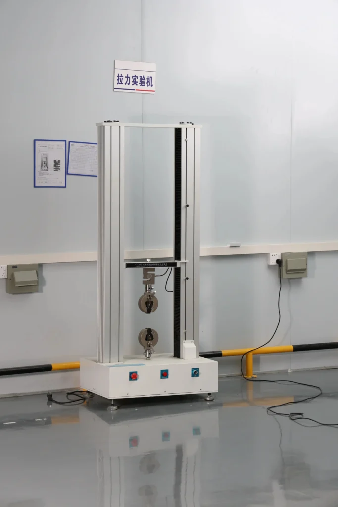
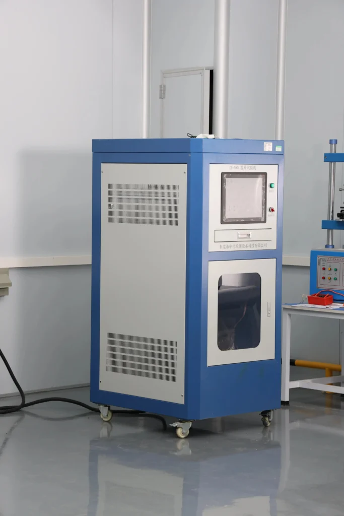
VoltixC is UL certified, its CE attestation under the Low Voltage Directive 2014/35/EU covers the full terminal range with the TC4008 included, and it has a RoHS test report available (SGS). The documents name Guangzhou FuTeXin Technology Co., Ltd., the company behind the VoltixC brand, whose Guangzhou factory has 1,200 m² of floor space, 25 staff and 135 production machines.
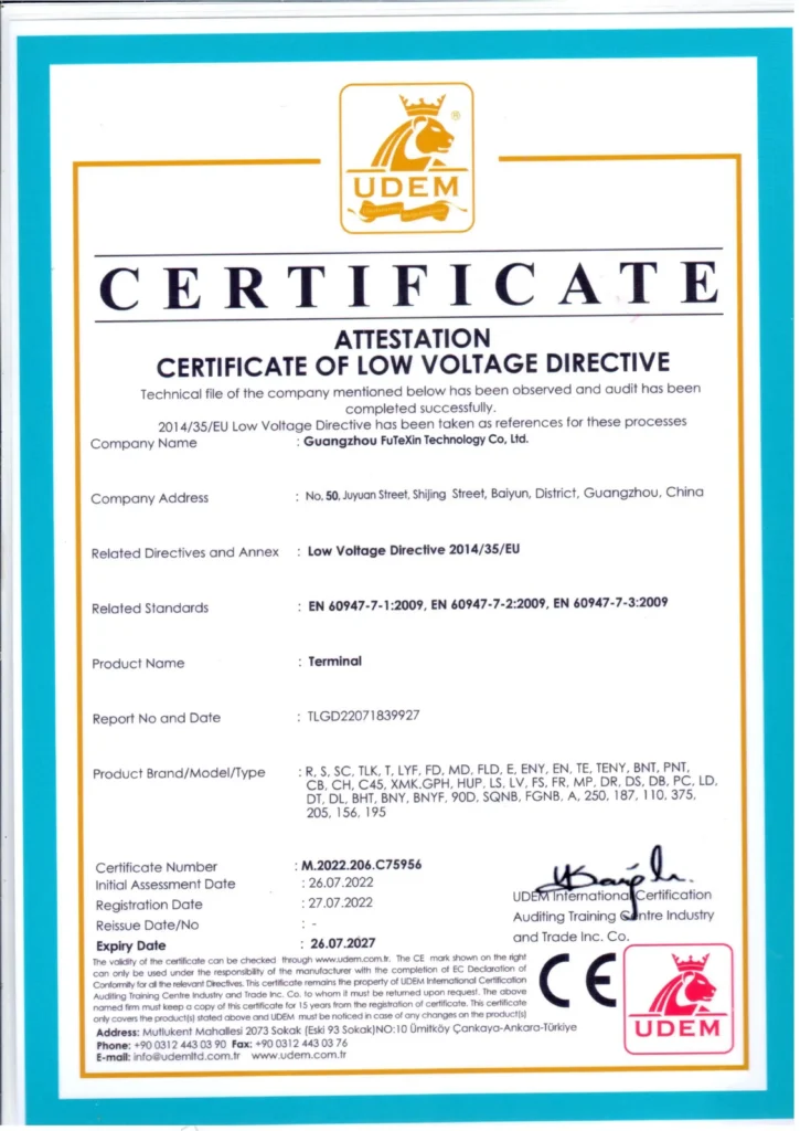
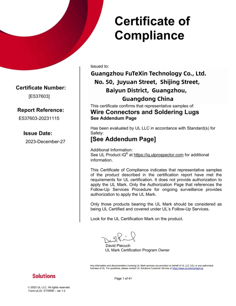
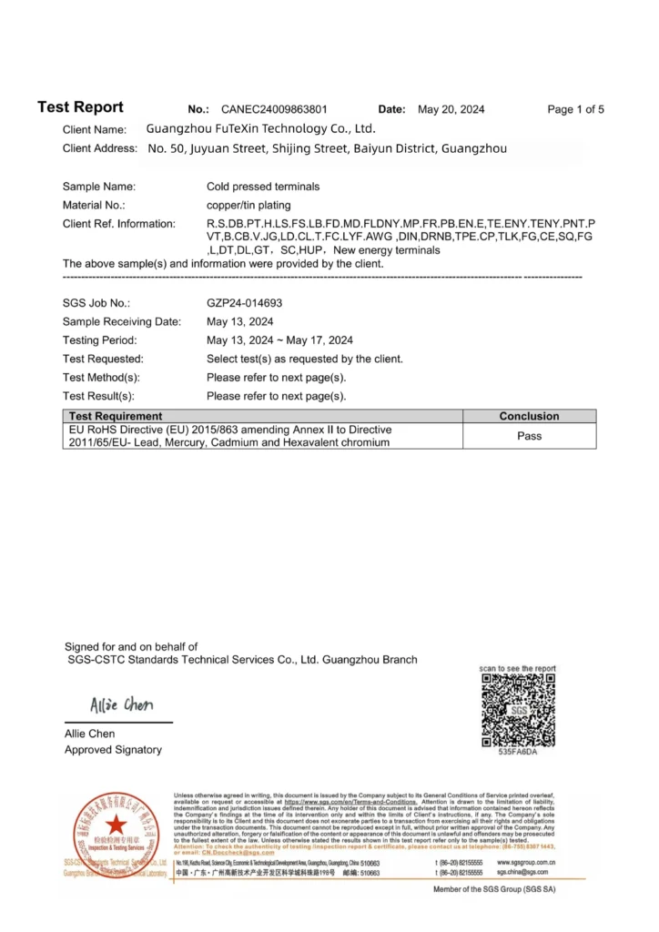
The CE attestation lists EN 60947-7-1, EN 60947-7-2 and EN 60947-7-3, and the SGS report covers lead, mercury, cadmium and hexavalent chromium on a tin-plated copper terminal sample. Numbers and dates are not printed on this page, and none of the images shows a grounding and bonding listing for the TC4008. Ask for the document copy that matches your order if your buyer or inspector needs one.
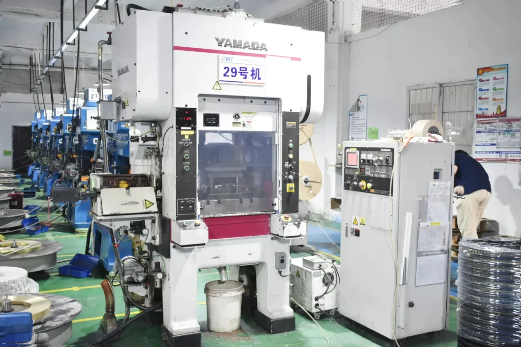
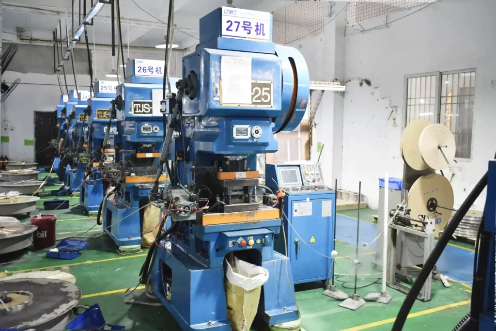
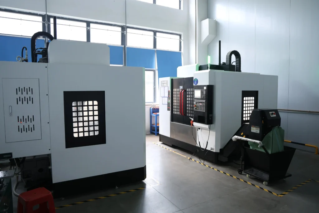
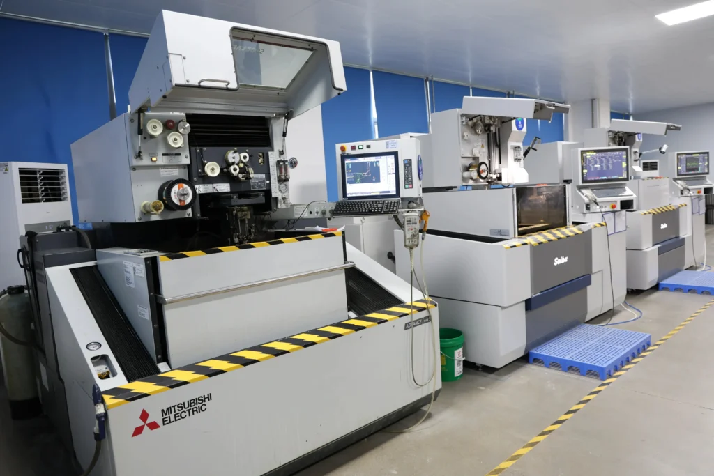

Before a C-tap goes into a specification, get these four points settled by the supplier, VoltixC or another:
The price of a C-tap connector order follows the conductor pair first, because the pair sets the body size and the copper in each part. Finish, marking, covers, packing and quantity then move the figure up or down. Each driver below is something you fix in the enquiry.
| Driver | Effect on cost | What you control |
|---|---|---|
| Run and tap conductor pair | A larger pair needs a larger body and more copper per part | Send both sizes for every joint type |
| Body metal | Copper is the listed body; another metal changes the material line | State the metal your specification requires |
| Finish | Tin plating adds a process step over bare copper | Choose tin-plated or bare |
| Die code or color marking | Marking the die reference on the body adds a step | Say whether your installers need a marked part |
| Insulation cover | A cover supplied with the part is a second item on the quote | Say whether covers ship with the connectors |
| Packing and labels | Private labels and custom cartons add packing work | Send label text and carton counts |
| Order quantity | Setup work is spread over the quantity of each size pair | Give the quantity per size pair for the whole supply |
| Drawing-based changes | A new body shape needs tooling before production | Send the drawing and the target conductor pair |
| Documents for the shipment | Certificate copies and other papers your buyer asks for add paperwork | List the documents with the enquiry |
Commercial terms are handled the same way for every part on this site: MOQ, payment terms, delivery terms and lead time are confirmed per order by email or the enquiry form. This page carries no figures for them.
If you are comparing suppliers, send each one the same list: conductor pair, body metal, finish, marking, cover, packing and quantity. Price gaps then come from the part itself rather than from different assumptions about what was asked.
If you want a TC4008 in hand before the bulk order, fastest sampling is 7 days. A sample lets you try the die fit on your own tool first.
Drawings and conductor photos go by email to hugo@voltixconnect.com, since the enquiry form has no upload field. Mention the model number TC4008 in the subject line so the files join the right enquiry.
Three pages help you prepare the size pair and the crimp details before you send a C-tap enquiry.
Find lug sizes by conductor size with the cable lug size chart, and write your run and tap sizes into the enquiry in one unit.
The wire terminal crimping guide covers die choice, stripping and pull checks for crimped parts in general.
The choosing cable lugs guide explains the main lug types, which helps when one job mixes taps and terminations; the lugs themselves are listed across the copper cable lug range.
With a compression tool fitted with the die the connector maker specifies. According to the ILSCO installation guide, colored bands, dots or stamped die codes may identify that die. The TC4008 supplier record lists no die reference, so ask for it with the quote and check it against your tool. VoltixC does not recommend a tool brand.
Branch joints off a continuous copper run, and parallel joints between two conductors, made without cutting the run. They suit taps where both the run and the tap sit inside one part’s range. Grounding electrode conductor splices and taps are a separate case that needs a grounding and bonding listing.
None are listed: the supplier data for the TC4008 gives one model and a copper body with no run or tap range. Send the run size, the tap size and the stranding for each joint, and each pair is checked against the part before the quote.
The die can differ. A C crimp takes the die its maker names, which may not be the one used for lugs or splices. According to Thomas & Betts, C-taps are color coded to prevent mismatching the installing die and connector, and improper dies may cause the connector to fail in service. One tool body can serve both jobs if it accepts the right die.
Only if the part is listed as grounding and bonding equipment. The NEC text reproduced by the ICC, section 250.64(C)(1), permits splicing a wire-type grounding electrode conductor only by irreversible compression-type connectors with that listing, or by an exothermic connection. The TC4008 supplier data shows no such listing, so don’t use it there.
Start from both conductors, not one. According to Thomas & Betts, each C-tap covers a range of conductor sizes. Write down the run size and the tap size in AWG, kcmil or mm², add the stranding, and pick the part whose confirmed range holds both. For the TC4008, send both sizes with the enquiry and the range is set against them.
Neither, as listed: the supplier data gives a copper body with no plating and no insulation. The finish is tin-plated or bare copper to your requirement. A cover is a separate item; according to Thomas & Betts, its C-tap instruction sheet lists shrink tubing and adhesive insulation choices for each C-tap size.
Yes. VoltixC takes on drawing-based work; send the drawing with the run and tap pair it must hold, the finish and the quantity. A new body shape needs tooling before production, and whether that tooling makes sense depends on the order quantity. The listed TC4008 stays the starting point for comparison.
No. The model number TC4008 and the copper body come from supplier data as listed and haven’t been individually re-tested. The typical values in the parameter table restate published references, not tests on the TC4008, and no rating is stated for the TC4008. The same table shows which TC4008 values are customizable: the finish, the cover and the die marking.
Send the run size, tap size, conductor metal, die family and quantity for each joint, and the reply says whether the TC4008 covers that pair.