VOLTIXC / ENQUIRY
Request a Quote
Tell us what you need and we will review your enquiry.

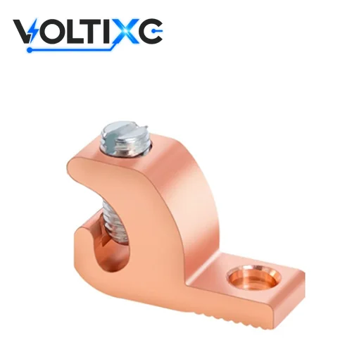
Lay-in ground lug with an open channel and a set screw, for bonding one continuous conductor to racks, enclosures and equipment frames.
Fast answer: Grounding lugs connect a bonding or grounding conductor to equipment, racks or panels. A lay-in ground lug has an open channel, so a continuous conductor can be laid in and clamped with a set screw without cutting it. VoltixC lists eight lay-in catalogue numbers here, from 14 AWG to 250 kcmil on #10 to 5/16 in bolts; request a quote with your conductor size.
This page covers one lay-in series with eight catalogue numbers in four wire ranges: 14–4 AWG, 8–1/0 AWG, 6–3/0 AWG and 6 AWG–250 kcmil. The supplier specification sheet gives the bolt size and five drawing dimensions for each one, and the body metal is settled on the quotation.
| At a glance | Supplier data as listed |
|---|---|
| Series on this page | 1 lay-in series |
| Catalogue numbers | 8 (ALL and CLL, four sizes each) |
| Wire range | 14 AWG to 250 kcmil |
| Material | Terminal body listed as aluminum alloy, tin-plated; confirmed per order |
A lay-in grounding lug holds a bare conductor in an open channel under a set screw, while the lug body is bolted to the metal part being grounded. The channel is open at the top, so the installer drops the conductor in partway along a run instead of feeding a cut end into a closed barrel. One bare conductor can then pass through several lugs and bond a row of frames. Ground lugs and lay in lugs are the shorter trade names for these parts.
The lug body is fastened to the equipment, rail or enclosure with one bolt; the model table gives the bolt size for each catalogue number.
The bare conductor, solid or stranded electrical wire, is laid into the open channel without cutting the run.
The set screw is tightened onto the conductor to the torque the lug maker gives for that conductor size.
The conductor carries on to the next lay-in lug or to the grounding bar.
The connection has an electrical job first. According to a Mike Holt excerpt covering NEC Article 250.4(A)(5), earth is not suitable as the effective ground-fault current path, so an equipment grounding conductor recognized in 250.118 is required with all circuits. Each lug on that conductor is a joint in the fault path, and the set-screw torque for this lug is not stated in the supplier data; ask before you specify.
The product standard for this class of part is UL 467. It covers equipment that connects power-system grounding conductors, non-current-carrying metal parts of equipment, armored grounding wires or metal raceways to grounding electrodes. Its scope names ground clamps, bonding devices, grounding bushings, water-meter shunts and grounding electrodes. That scope describes the product class; VoltixC does not claim UL 467 certification for this lay-in lug.
Grounding lugs for a lay-in run are matched on conductor size, channel form, mounting hole, then body and plating, in that order. The model table below answers the first and third checks for each catalogue number; the other two depend on what you send.
Conductor size and type. Find your size in the wire range column: 14–4 AWG, 8–1/0 AWG, 6–3/0 AWG or 6 AWG–250 kcmil. Say whether the bare copper conductor is solid or stranded.
Channel form. Confirm that the conductor must pass through without a cut. If it ends at the lug, a closed barrel suits the job better, as the route comparison below shows.
Mounting hole and surface. Match the bolt size in the table (#10, 1/4 in or 5/16 in) to your frame, and name the metal of the frame, rail or enclosure the lug will sit on.
Body and plating. The supplier description lists an aluminum alloy body with tin plating. If your specification calls for copper ground lugs with a copper body, say so in the enquiry; a copper body is a special request, so ask before you specify.
Set-screw torque changes with conductor size, and the value comes from the lug maker, not from a general chart. Use the value marked on the lug or given in the maker’s installation instructions, which is where NEC 110.14(D) points for terminal torque. The supplier sheet prints no torque, so the value for each VoltixC lay-in lug comes with its drawing.
Send My Size ListEight lay-in grounding lug catalogue numbers are listed, in four wire ranges from 14 AWG to 250 kcmil. Each row gives the bolt size and the five dimensions printed on the supplier specification sheet, with inches converted to mm.
| Cat. No. | Wire range (AWG / kcmil) | Bolt size (in) | A, mm (in) | C, mm (in) | D, mm (in) | F, mm (in) | H, mm (in) |
|---|---|---|---|---|---|---|---|
| ALL0414 | 14–4 AWG | #10 | 26.92 (1.06) | 9.65 (0.38) | 4.09 (0.161) | 4.83 (0.19) | 19.05 (0.75) |
| CLL0414 | 14–4 AWG | #10 | 26.92 (1.06) | 9.65 (0.38) | 4.09 (0.161) | 4.83 (0.19) | 19.05 (0.75) |
| ALL1038 | 8–1/0 AWG | 0.25 (1/4) | 38.10 (1.50) | 16.00 (0.63) | 5.00 (0.197) | 7.62 (0.30) | 28.70 (1.13) |
| CLL1038 | 8–1/0 AWG | 0.25 (1/4) | 38.10 (1.50) | 16.00 (0.63) | 5.00 (0.197) | 7.62 (0.30) | 28.70 (1.13) |
| ALL3012 | 6–3/0 AWG | 0.3125 (5/16) | 50.80 (2.00) | 20.57 (0.81) | 5.99 (0.236) | 10.16 (0.40) | 38.10 (1.50) |
| CLL3012 | 6–3/0 AWG | 0.3125 (5/16) | 50.80 (2.00) | 20.57 (0.81) | 5.99 (0.236) | 10.16 (0.40) | 38.10 (1.50) |
| ALL2512 | 6 AWG–250 kcmil | 0.3125 (5/16) | 55.63 (2.19) | 20.57 (0.81) | 6.50 (0.256) | 10.16 (0.40) | 42.93 (1.69) |
| CLL2512 | 6 AWG–250 kcmil | 0.3125 (5/16) | 55.63 (2.19) | 20.57 (0.81) | 6.50 (0.256) | 10.16 (0.40) | 42.93 (1.69) |
Data note: all eight rows are per supplier specification sheet and have not been individually re-tested. ALL and CLL catalogue numbers of the same wire range share every printed dimension; the sheet does not say what the two prefixes stand for, and it prints no body metal or plating.
Source: supplier specification sheet for the lay-in series (Cat. Nos table; dimensions printed in inches).
These 8 part numbers are the full specification table for the series; request the dimensioned drawing with your quote.
| Column | How to read it |
|---|---|
| Cat. No. | Catalogue number as printed; quote it in your enquiry |
| Wire range (AWG / kcmil) | The SAE cable wire gauge range the channel takes; sizes above 4/0 AWG are in kcmil. Your project specification sets the conductor size, whatever load the circuits carry |
| Bolt size (in) | The bolt that fixes the lug body: a #10 screw, 0.25 in (1/4) or 0.3125 in (5/16) |
| A, C, D, F, H | Letter dimensions from the supplier drawing, in mm with the printed inch value in brackets; ask for the drawing that marks each letter on the lug |
| Standard pack | 100 pieces per box for every catalogue number |
| Common names | Lay-in lug, lay-in ground lug, ground terminal connector |
Terminal body listed as aluminum alloy, tin-plated; confirmed per order, which is how the supplier product description gives it. An older family record for the same lug says copper, and the specification sheet prints no metal for any of the eight catalogue numbers. Since the files don’t agree, you settle the body material on the quotation.
| Place in the supplier record | What it says | How this page uses it |
|---|---|---|
| Supplier family record | Terminal material: copper | Not used on this page; the conflict is noted for the supplier |
| Specification sheet, 8 Cat. Nos | No body metal or plating printed | Model table shows sizes only |
| Product description, terminal body | Aluminum alloy | Used for the body line on this page |
| Product description, plating | Tin-plated | Stated as supplier data; finish checked on the sample |
The conductor and the set screw bear on the plated surface. The supplier description names tin but gives no thickness, so this page prints none. If your frame or rail maker names a finish, send it with the enquiry.
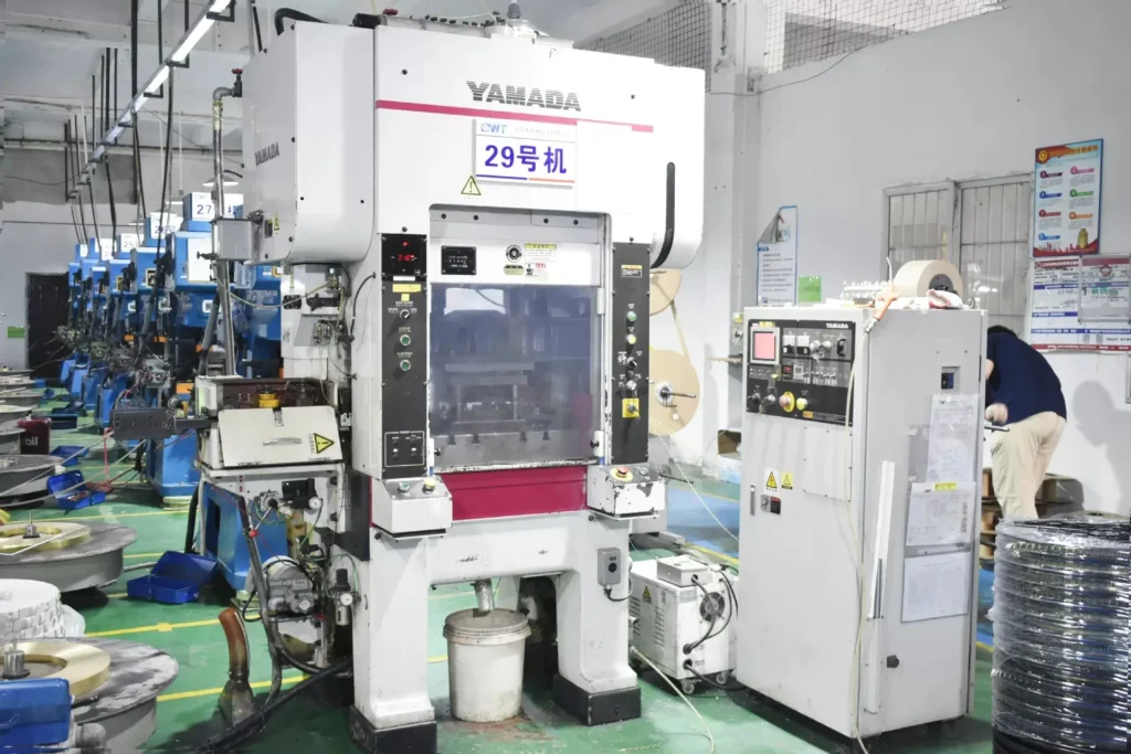
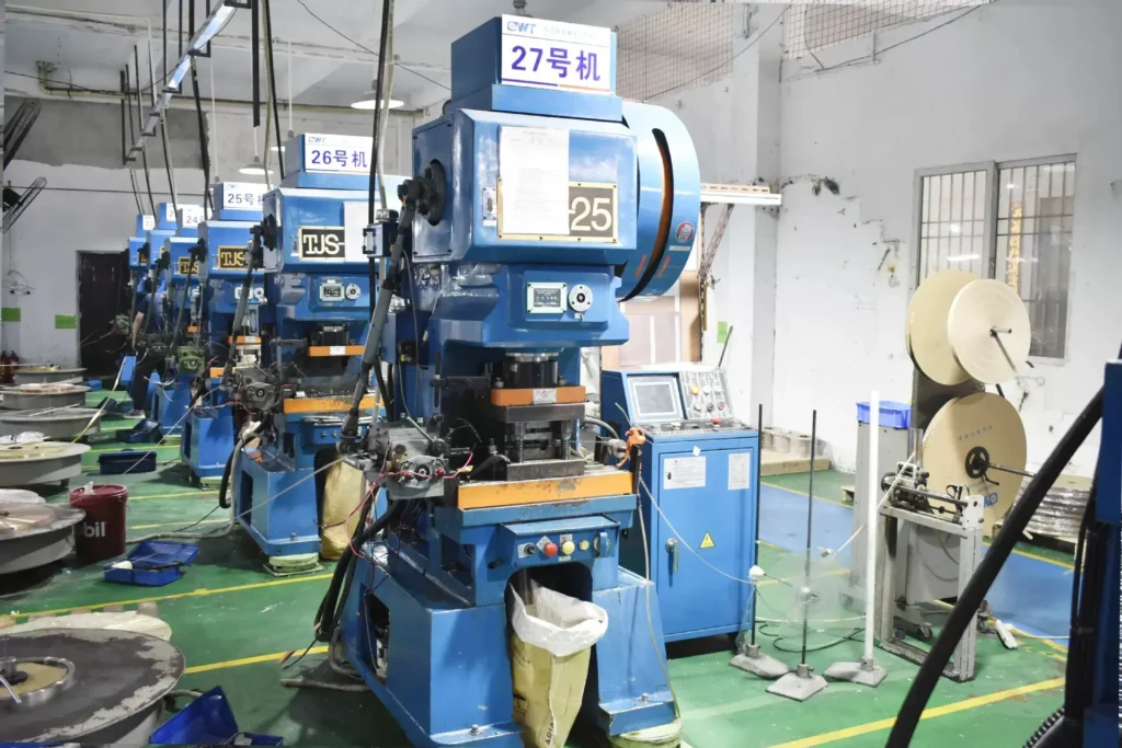
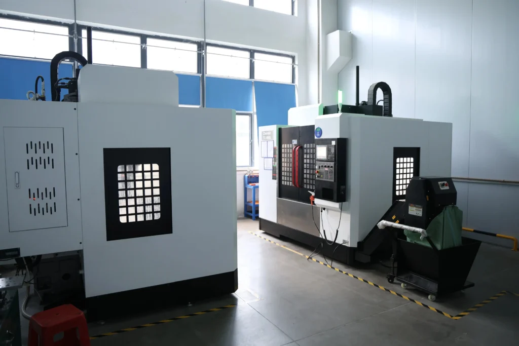
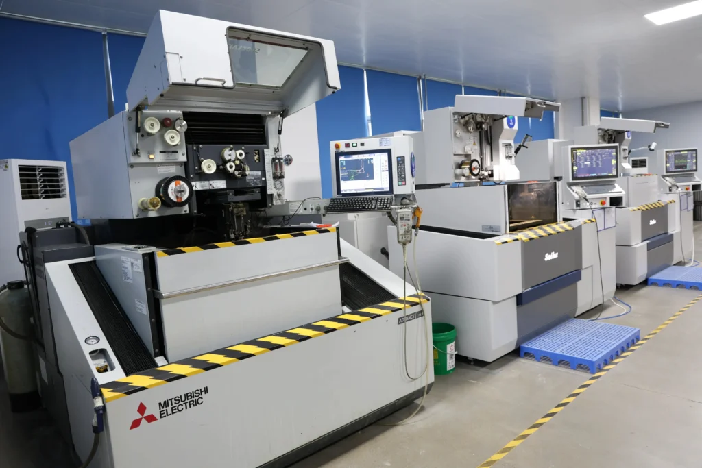
Further down, the factory photos include stamping presses, a CNC milling machine, wire-cut EDM and grinders for tooling. The test equipment in them covers a tensile tester, a temperature-rise tester and an optical CMM. They show what is on site, and they aren’t a test record for this lay-in lug.
Pick the lay-in ground lug when one bare conductor has to pass through several ground points without a cut; pick a closed-barrel or crimped part when the conductor ends at the lug. The four routes below all land a conductor on metal, and each one belongs to a different page of the mechanical lugs range or its guides.
| Route | How the conductor is held | Choose it when | Where to look |
|---|---|---|---|
| Lay-in ground lug (open-channel style) | Open channel and set screw; conductor laid in mid-run | A continuous bonding conductor links several frames, rails or enclosures | This page |
| Closed-barrel set-screw lug | Conductor end pushed into a closed barrel under a screw | The conductor terminates at a breaker, bus or equipment pad | closed-barrel mechanical lugs |
| Double or stacked lug | Two conductors held at one mounting point | Two conductors must land at one point | stacked two-conductor lugs |
| Compression lug | Barrel crimped onto the conductor end with a matched die | The site calls for a tool-made, permanent termination | crimp vs set-screw guide |
A lay-in lug is a mechanical ground lug. Its set screw supplies the clamping force, so the finished joint depends on the torque applied on site. A crimped part moves that check to the tool and die. On an electrician forum, a user with a 4 AWG bare copper grounding electrode conductor asked which tool and die were correct and whether tool and connector should come from the same brand. That’s a compression-route question; on the lay-in route you ask about set-screw torque instead.
Use another page if:
Switching also changes the enquiry. For a closed barrel, send the conductor range per barrel; a double lug quote takes both conductor sizes, and a compression lug quote starts from the die series your installers hold.
Lay-in grounding lugs fit jobs where one bare conductor bonds several metal parts in a row. The use categories below come from the shape of the part and from the grounding texts cited on this page; VoltixC publishes no project reference for them.
Requirement: every metal enclosure or rack on the run is tied into the fault path. According to a Mike Holt excerpt covering NEC Article 250.4(A)(3), metal parts of raceways, cables, enclosures and equipment must connect to the supply source through an effective ground-fault current path.
Fails when: the lug body sits on paint instead of bare metal, or the set screw stays below the maker’s torque.
Requirement: one continuous bare conductor passes through each lug and ends at the grounding bar. The open channel lets the installer add or move a lug without cutting the run.
Fails when: the conductor is larger or smaller than the channel range confirmed on the drawing.
Requirement: the racking or module maker’s grounding instructions name the lug, the conductor and the fastening point. The supplier description gives an aluminum alloy body with tin plating; check that pairing against the frame metal with the racking maker.
Fails when: the maker’s instructions call for one named part and a different lug is fitted.
A conductor that stops at a breaker or bus pad needs a closed barrel. The copper mechanical lugs page covers that job.
UL 467 includes intersystem bonding terminations for connecting the bonding and grounding conductors of other systems in accordance with NFPA 70. Those are a named product of their own; a single lay-in lug is not quoted for that role.
The supplier record gives no rating for direct burial or encasement, so this lay-in lug is not offered for a grounding electrode joint below grade. Ask for a part made and marked for that use.
For grounding lugs sold into North America, the reference standard is UL 467; VoltixC’s own CE, UL and RoHS documents are listed under the images below. According to the UL Standards product page, UL 467 applies to grounding and bonding equipment used under CSA C22.1 in Canada, NFPA 70 in the United States or NOM-001-SEDE in Mexico. According to UL Solutions, grounding and bonding equipment is evaluated to UL 467, with support for Canada and Mexico where applicable.
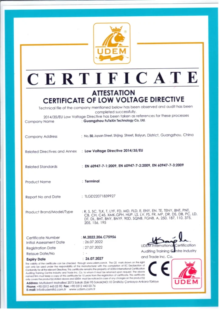
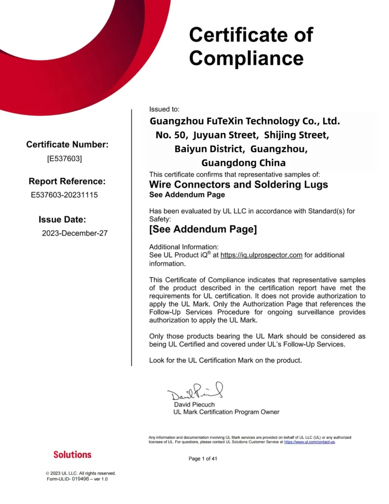
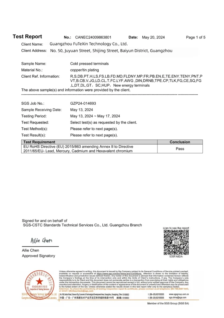
VoltixC is UL certified. The CE attestation under LVD 2014/35/EU, assessed against EN 60947-7-1, EN 60947-7-2 and EN 60947-7-3, covers the full terminal range, these lay-in lugs included. RoHS test report available (SGS), covering lead, mercury, cadmium and hexavalent chromium. All three documents are issued to Guangzhou FuTeXin Technology Co., Ltd., the company behind the VoltixC brand. Numbers and dates are not printed here, and this page does not state that the lug has been evaluated to UL 467.
Standards named for one product family can differ from item to item. As one example, ILSCO Form 2 names UL 486A-B and UL 467 for its CP-8, CP-4, CP-0 and CP-250 connectors, and UL 486A-B alone for CP-500 and CP-1000, which are also not for compact copper wire. In a Mike Holt forum thread on grounding electrode conductor splices and taps, the connector’s grounding and bonding listing was treated as the main selection question. That question heads the list below.
Get a written answer to each line before you approve a sample from this factory or from another:
| Ask the supplier | A useful answer names |
|---|---|
| Is this exact item evaluated to UL 467, or only to a connector standard? | The standard, the item number and the document that shows both |
| Which conductor sizes, and how many conductors, does the channel take? | A range in AWG or mm² tied to the drawing |
| What torque does the set screw take for my conductor size? | One value per size, on the drawing or the label |
| What are the body and plating materials? | The metal or alloy and the plating type, per order |
The equipment photos below were taken at the Guangzhou plant, which has a 1,200 m² floor and 135 production machines. They show equipment on site, not a test report for this lug.
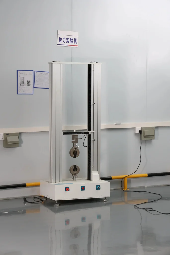
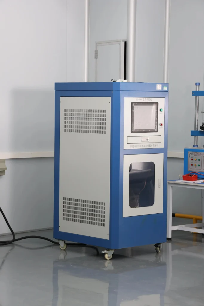
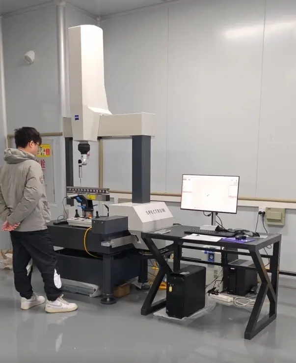
The price of a lay-in grounding lug moves with seven inputs you fix in the enquiry, from conductor range to paperwork. Lead time, MOQ and payment are confirmed per order by email or the enquiry form, so none of them is printed here.
| Driver | Effect on cost | What you control |
|---|---|---|
| Conductor range | A larger channel takes more metal and a larger set screw | The conductor size and type you state |
| Body material | An aluminum alloy body and a copper body are priced apart | Accepting the listed aluminum alloy body or asking for another |
| Plating | Plating adds a finishing step to every piece | Whether the listed tin plating suits your frame metal |
| Mounting hole and footprint | A hole or footprint away from the listed part may need new tooling | The bolt size and frame drawing you send |
| Tooling | A changed shape needs tooling before production starts | Staying on the listed form, or signing off a drawing for a new one |
| Quantity and packing | Batch size spreads the setup work across more pieces | Order quantity and pieces per bag or carton |
| Documents | Extra paperwork per shipment adds handling time | The documents you need with the goods |
Distributors stocking a range can list each conductor size they plan to carry with a quantity per size, and the quotation then prices each line on its own. Private labels, bag counts and carton marks belong in the same first message, because packing is one of the cost inputs in the table above. If the lug has to match a part already in your catalogue, name that part and send its drawing so the body, channel and screw can be compared line by line.
An enquiry for this lay-in lug moves like this:
The enquiry form collects contact details (name, company, email, country) and order details (product line, conductor size, quantity), plus a message. With no upload field on it, drawings or frame photos go by email to hugo@voltixconnect.com. Tooling for a new channel or footprint starts only after you sign the drawing.
This site has no sizing tool for lay-in lugs, so three guides cover the checks around this part instead.
The guide to grounding connector types sorts ground lugs, clamps and bonding parts by the job they do, from a bonding lug on a frame to a clamp on an electrode.
The compression vs mechanical lugs guide sets a crimped termination beside a set-screw one, for readers weighing the two routes compared above.
The torque guide for set-screw lugs explains how a set-screw lug maker states torque per conductor size, the value asked for in the checks above.
Four wire ranges are listed: 14–4 AWG (ALL0414 / CLL0414), 8–1/0 AWG (ALL1038 / CLL1038), 6–3/0 AWG (ALL3012 / CLL3012) and 6 AWG–250 kcmil (ALL2512 / CLL2512). Pick the range that holds your wire gauge, and say whether the wire is solid or stranded. The set-screw torque for that size comes with the drawing.
Tin plating is listed in the product description. The specification sheet prints no plating and no thickness, so judge the finish on the sample. If your frame maker names another finish, put it in the enquiry.
Terminal body listed as aluminum alloy, tin-plated; confirmed per order. That is the supplier product description; an older family record says copper, and the specification sheet names no metal. Where your specification calls for a copper body, write that into the enquiry, and the quotation names the body metal on offer.
Only the lay-in type takes a conductor mid-run: its channel is open at the top, and a set screw clamps the wire once it is laid in. A standard ground lug terminal has a closed barrel that accepts the conductor end only. For one conductor bonding several points in a row, use the lay-in form; where the conductor stops at the lug, the closed barrel is the better fit.
Your project specification decides whether that mark is required. UL 467 is the product standard for grounding and bonding equipment in the United States, Canada and Mexico. UL Solutions notes that listings that meet the applicable U.S. and Canadian requirements can carry a UL/C-UL Listing Mark. Before you approve a sample, ask which document covers the exact item you order.
Tighten it to the torque marked on the lug or stated in the maker’s installation instructions for your conductor size (NEC 110.14(D)). Another brand’s chart doesn’t apply to this part. For this lay-in lug the value is confirmed per order and printed on its drawing. On a run where one bare conductor passes through several lay-in lugs, log the figure for each lug on the installation sheet, so every set screw along the run can be checked against it.
The supplier data for this lay-in lug states no rating for more than one conductor per channel, so it is quoted for one conductor. When two conductors must land at one point, pick a part from the double lugs page.
Eight catalogue numbers are listed, ALL and CLL versions of four sizes, all per supplier specification sheet. The wire ranges, bolt sizes and A, C, D, F and H dimensions haven’t been individually re-tested. The sheet lists a standard pack of 100 pieces per box for each one. Torque and body metal are not on the sheet and come with the drawing.
Seven days is the fastest sampling time VoltixC gives. Tooling comes first if you change the channel or footprint, and production lead time is confirmed per order.
Send the conductor size, the frame or stud details, the number of ground points and the quantity, and quote the Cat. No. from the model table. Drawings and photos go by email, since the form has no upload field. The reply lists the points still open on body material, plating and torque.
Ask a VoltixC Engineer