VOLTIXC / ENQUIRY
Request a Quote
Tell us what you need and we will review your enquiry.

Non insulated butt connectors and parallel splices in bare copper, for joining two cables inline or side by side.
Fast answer: Non insulated butt connectors are bare copper compression splices that join two conductors inside one crimped barrel: end to end in a butt splice, or side by side in a parallel splice. VoltixC lists three series with 126 part numbers, from 26-22 AWG up to 1000 kcmil. For vinyl or nylon insulated splices, see the insulated butt splice page.
The range runs from BNT0.5 and PNT0.5 at 26-22 AWG to DS1152 at 1000 kcmil. Every value in the model tables below comes from the supplier specification sheets; a size that is not on the sheets is a drawing request, so ask before you specify it.
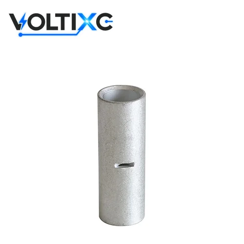
A non insulated butt connector joins two cables by compression: both stripped conductor ends go into one copper barrel, and a die presses the barrel onto them. According to Electrical Engineering Portal, a crimp connection places the conductors into a tubular opening and mechanically presses or deforms the tube onto the conductor. The joint has no palm and no bolt, so the splice itself carries the current from one cable to the other.
The three series on this page differ in how the conductors enter the barrel:
DS / LS compression butt splice. A straight copper tube; one cable enters from each end, from 8 AWG up to 1000 kcmil.
BNT butt splice. The same end-to-end joint in 13 AWG sizes, from BNT0.5 (26-22 AWG) to BNT100 (4/0 AWG).
PNT parallel splice. Both conductors enter from one side and lie next to each other inside the barrel, in the same 13 AWG sizes as BNT.
Losses start with a mismatch. A barrel sized for a larger conductor leaves the strands loose after crimping, and a barrel that is too small will not take all the strands. A copper splice on aluminum wire is a second failure path, covered in the model table section below. Sharp flash left by the die can cut through tape or sleeving applied over the joint later.
For buyers in Europe, IEC 61238-1-1 is the reference test standard: it applies to compression and mechanical connectors for power cables up to 1 kV (Um = 1.2 kV) on non-insulated conductors. Naming the standard here describes the product class; it is not a claim that a given VoltixC part holds a test report to it.
VoltixC lists non insulated butt connectors and parallel splices in three series, and the two tables below follow the supplier specification sheets. The DS / LS sheet gives 100 compression butt splices across 19 wire sizes, from 8 AWG to 1000 kcmil. The BNT and PNT sheets give 13 parts each, from 26-22 AWG to 4/0 AWG, and all 26 are in the second table.
Pick the splice by conductor size and conductor material first. According to Panduit, installers should use a compression connector marked for the wire size and wire material, and never a copper connector on aluminum wire. For scale, according to UL Standards & Engagement, the copper conductor ranges covered by UL 486A-486B are 30 AWG through 10 AWG solid and 30 AWG through 2,000 kcmil stranded. That range describes the standard’s scope only; it says nothing about certification of the parts below.
DS and LS are the heavy end of the page: straight copper tubes for 8 AWG to 4/0 AWG and 250 to 1000 kcmil cable, with a die color and a die code printed for each catalog number. Most wire sizes come as a short DS and a longer LS, and several add -41, -50 or -60 versions with their own length A or ID (barrel inside diameter). The table gives one row per wire size; the last column names the other part numbers printed for that size.
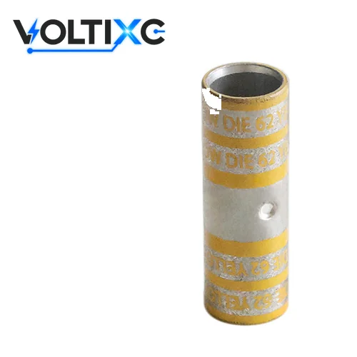
| Cat. No. | Wire size | Length A, mm (in.) | ID, mm (in.) | Die color | Die code | Other part numbers on the sheet |
|---|---|---|---|---|---|---|
| DS0821 | 8 AWG | 25.65 (1.01) | 4.57 (0.18) | Red | 21 | DS0821-50, LS0821, LS0821-50 |
| LS0624 | 6 AWG | 44.96 (1.77) | 5.59 (0.22) | Blue | 24 | DS0624-50, DS0624-60, LS0624-50, LS0624-60 |
| DS0429 | 4 AWG | 25.65 (1.01) | 6.86 (0.27) | Grey | 29 | DS0429-50, DS0429-60, LS0429, LS0429-50, LS0429-60 |
| DS0233 | 2 AWG | 32.00 (1.26) | 7.62 (0.30) | Brown | 33 | DS0233-50, DS0233-60, LS0233, LS0233-50, LS0233-60 |
| DS0137 | 1 AWG | 38.61 (1.52) | 9.14 (0.36) | Green | 37 | DS0137-50, DS0137-60, LS0137, LS0137-50, LS0137-60 |
| DS1042 | 1/0 AWG | 41.91 (1.65) | 10.16 (0.40) | Pink | 42 | DS1042-50, DS1042-60, LS1042, LS1042-50, LS1042-60 |
| DS2045 | 2/0 AWG | 44.96 (1.77) | 11.18 (0.44) | Black | 45 | DS2045-50, DS2045-60, LS2045, LS2045-50, LS2045-60 |
| LS3050 | 3/0 AWG | 57.66 (2.27) | 12.95 (0.51) | Orange | 50 | DS3050-41, DS3050-50, LS3050-50 |
| DS4054 | 4/0 AWG | 48.26 (1.90) | 14.22 (0.56) | Purple | 54 | DS4054-50, DS4054-60, LS4054, LS4054-50, LS4054-60 |
| DS2562 | 250 kcmil | 57.66 (2.27) | 16.00 (0.63) | Yellow | 62 | DS2562-41, DS2562-50, DS2562-60, LS2562, LS2562-50, LS2562-60 |
| Cat. No. | Wire size | Length A, mm (in.) | ID, mm (in.) | Die color | Die code | Other part numbers on the sheet |
|---|---|---|---|---|---|---|
| DS3166 | 300 kcmil | 54.61 (2.15) | 17.78 (0.70) | White | 66 | DS3166-50, DS3166-60, LS3166, LS3166-50, LS3166-60 |
| DS3571 | 350 kcmil | 57.66 (2.27) | 19.05 (0.75) | Red | 71 | DS3571-50, DS3571-60, LS3571-50, LS3571-60 |
| DS4176 | 400 kcmil | 70.61 (2.78) | 20.07 (0.79) | Blue | 76 | DS4176-50, DS4176-60, LS4176, LS4176-50, LS4176-60 |
| DS5187 | 500 kcmil | 70.61 (2.78) | 22.35 (0.88) | Brown | 87 | DS5187-50, DS5187-60, LS5187, LS5187-50 |
| DS6194 | 600 kcmil | 76.96 (3.03) | 24.38 (0.96) | Green | 94 | DS6194-50, DS6194-60, LS6194, LS6194-50, LS6194-60 |
| DS7199 | 700 kcmil | 83.31 (3.28) | 24.64 (0.97) | Pink | 99 | DS7199-41, DS7199-60 |
| LS7561 | 750 kcmil | 121.92 (4.80) | 26.92 (1.06) | Black | 106 | DS7561-50, DS7561-60, LS7561-41, LS7561-50, LS7561-60 |
| LS9151 | 900 kcmil | 141.22 (5.56) | 30.23 (1.19) | Yellow | 115 | — |
| DS1152 | 1000 kcmil | 93.22 (3.67) | 31.75 (1.25) | N/A | 125 | DS1152-50, DS1152-60, LS1152, LS1152-50, LS1152-60 |
Source: per supplier specification sheet; length A and ID are printed in inches and converted to mm; values not individually re-tested. 100 part numbers in the full specification table — request the complete list with your quote.
BNT is the butt splice: the two conductors enter from opposite ends of one barrel, and the cable run carries on in a straight line. The BNT and PNT sheets print a copper body with tin plating and list the same 13 wire ranges, from 0.2-0.5 mm² (26-22 AWG) to 100 mm² (4/0 AWG).
PNT is the parallel splice connector: both conductors enter from the same end and lie side by side, so the run stops at the joint. A PNT part is shorter than the BNT part for the same range, and the barrel ID and OD match on every range except 12-10 AWG.
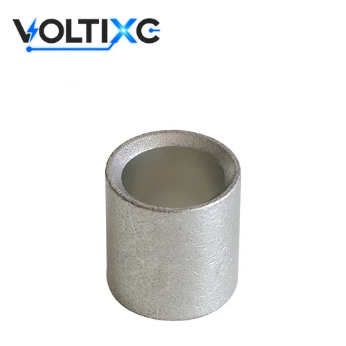
| Part No. | AWG | mm² (as printed) | Length L (mm) | Barrel ID d (mm) | Barrel OD D (mm) | Max. current (A) |
|---|---|---|---|---|---|---|
| BNT0.5 | 26-22 | 0.2-0.5 | 12 | 1.3 | 2.1 | 9 |
| BNT1 | 22-16 | 0.5-1.5 | 15 | 2.1 | 3.3 | 19 |
| BNT2 | 16-14 | 1.5-2.5 | 15 | 2.6 | 4 | 27 |
| BNT3 | 14-12 | 2.5-4 | 15 | 3 | 5 | 37 |
| BNT5 | 12-10 | 4-6 | 15 | 3.6 | 5.4 | 48 |
| BNT8 | 8 | 8 | 21 | 4.6 | 7 | 62 |
| BNT14 | 6 | 14 | 26 | 5.9 | 8.9 | 88 |
| BNT22 | 4 | 22 | 29 | 7.8 | 11.3 | 115 |
| BNT38 | 2 | 38 | 32 | 9.5 | 13.2 | 160 |
| BNT60 | 1/0 | 60 | 36 | 11.4 | 15.3 | 215 |
| BNT70 | 2/0 | 70 | 37 | 13.5 | 17.5 | 235 |
| BNT80 | 3/0 | 80 | 38 | 14.5 | 19.5 | 255 |
| BNT100 | 4/0 | 100 | 38 | 16.4 | 22.1 | 300 |
| Part No. | AWG | mm² (as printed) | Length L (mm) | Barrel ID d (mm) | Barrel OD D (mm) | Max. current (A) |
|---|---|---|---|---|---|---|
| PNT0.5 | 26-22 | 0.2-0.5 | 5 | 1.3 | 2.1 | 9 |
| PNT1 | 22-16 | 0.5-1.5 | 8 | 2.1 | 3.3 | 19 |
| PNT2 | 16-14 | 1.5-2.5 | 8 | 2.6 | 4 | 27 |
| PNT3 | 14-12 | 2.5-4 | 8.5 | 3 | 5 | 37 |
| PNT5 | 12-10 | 4-6 | 8.5 | 3.8 | 5.5 | 48 |
| PNT8 | 8 | 8 | 9.5 | 4.6 | 7 | 62 |
| PNT14 | 6 | 14 | 11 | 5.9 | 8.9 | 88 |
| PNT22 | 4 | 22 | 13.5 | 7.8 | 11.3 | 115 |
| PNT38 | 2 | 38 | 16.5 | 9.5 | 13.2 | 160 |
| PNT60 | 1/0 | 60 | 19 | 11.4 | 15.3 | 215 |
| PNT70 | 2/0 | 70 | 19 | 13.5 | 17.5 | 235 |
| PNT80 | 3/0 | 80 | 19.5 | 14.5 | 19.5 | 255 |
| PNT100 | 4/0 | 100 | 20 | 16.4 | 22.1 | 300 |
Source: per supplier specification sheets for BNT and PNT; the mm² figure is the one printed beside each AWG range; values not individually re-tested. All 26 BNT and PNT part numbers are listed.
Spec note None of the sheets gives a crimp count, and the DS / LS sheet prints no material grade or plating. Crimps per barrel, and plating on DS / LS parts, are confirmed per order. The maximum current column repeats the supplier’s printed value; it is not a VoltixC test result.
Choose copper butt connectors in two steps: decide whether the cables meet end to end or side by side, then match the conductor size to one row of the model tables. The matrix below maps each joint and size to the listed parts, with the size names buyers search for.
| Your joint | Listed sizes | Series and parts | Common names | Check before you order |
|---|---|---|---|---|
| Inline joint, small wire | 26-22 to 8 AWG | BNT0.5 to BNT8; DS0821 or LS0821 at 8 AWG | uninsulated butt connectors; bare butt connectors | The splice is bare; plan sleeving or pick an insulated part |
| Inline joint, 6 AWG | 6 AWG | BNT14; LS0624 or DS0624-50 | 6 gauge butt connector | Same wire size on both ends of the barrel |
| Inline joint, 4 AWG | 4 AWG | BNT22; DS0429 or LS0429 | 4 gauge butt connector; 4 awg wire connectors | Die code 29 on the DS / LS sheet; ask for the BNT die |
| Inline joint, 2 AWG | 2 AWG | BNT38; DS0233 or LS0233 | 2 gauge butt connector; 2 gauge connector; 2 gauge wire connectors; 2 ga wire connectors | Strand class of the cable |
| Inline joint, 1 AWG | 1 AWG | DS0137 or LS0137 (no BNT size) | 1 gauge wire connectors | Check the jacket print: 1 AWG is smaller than 1/0 |
| Inline joint, 1/0 AWG | 1/0 AWG | BNT60; DS1042 or LS1042 | 0 gauge connectors; 0 gauge wire connectors; wire connectors 0 gauge | Keep the slash in 1/0 on the size list |
| Battery cable splice, 2/0 to 4/0 AWG | 2/0, 3/0, 4/0 AWG | BNT70 to BNT100; DS2045, LS3050, DS4054 | battery cable butt connector; 2/0 butt connector | Copper cable only; send the strand class |
| Inline joint, large feeder | 250 to 1000 kcmil | DS / LS, 10 sizes | splice lugs; compression splice connector | Die code on the sheet; crimp count per order |
| Two conductors side by side | 26-22 AWG to 4/0 AWG | PNT0.5 to PNT100 | parallel splice connector | Both wires must fit the one listed range |
Borderline cases come in three kinds:
Size between two rows. Pick the row that names your exact size; if your conductor is not named, send its AWG or kcmil and strand count instead of rounding.
Two different cable sizes. A straight butt splice in the tables has one size for both ends; a reducing joint is a drawing request, quoted per order.
Fine-strand or flexible cable. Strand class changes how the barrel fills, so state it with the size; the crimp count is confirmed per order.
On a compression splice connector, the marks tell the installer which die to use and where to crimp. According to BURNDY, each connector is marked with the wire size and type, die index, and color coding. Those marks are the maker’s own system, so a die chart from one brand does not carry over to another brand’s barrel.
Two rows from one maker’s chart show how the system reads. According to ILSCO’s copper compression chart, the two sizes below use these codes:
| Example conductor (ILSCO chart) | Color code | Die | Crimps |
|---|---|---|---|
| #8 AWG Class B/C copper | Red | ILD-21 | 1 |
| 250 kcmil Class B/C copper | Yellow | ILD-62 | 1 |
These are ILSCO values for ILSCO parts. The DS / LS sheet prints the same color and number pairs for these two sizes: red and 21 for 8 AWG, yellow and 62 for 250 kcmil. It gives no crimp count, and a matching code alone does not show that another brand’s die fits.
Stripes on the barrel are spacing guides. According to Panduit, barrel stripes help space crimps evenly but do not designate the number of crimps. The crimp count comes from the die chart for the exact part.
The crimp profile is the last check. According to Klauke, quad-point indent crimping is suitable for tubular cable lugs and connectors from 10 to 300 mm². State the crimp profile your installers use when you send the size list, because the die and the profile are confirmed together per order.
Uninsulated butt connectors in this range have a copper body. The BNT and PNT sheets print tin plating; the DS / LS sheet does not state a finish. The bare barrel is the whole part, so the finish on site decides how the joint looks and how well it is covered.
Finishing a bare copper splice runs in four steps:
Crimp in the maker’s order. According to Panduit, the first crimp goes near the lug tongue or the wire stop of a splice, with successive crimps working toward the wire entry. Makers do not all use the same order, so follow the crimp order in the terminal maker’s instructions for the part you buy.
Remove flash and burrs. Thomas & Betts and Panduit instructions both say to remove sharp edges, flash or burrs left by the crimping dies after compression.
Insulate the joint. According to Panduit, heat-shrink insulation over a compression connector should overlap the wire insulation by at least 1-1/2 in and be shrunk from the crimped portion toward the insulated wire.
Check the die. Confirm that the die you used matches the chart for that exact part before the joint is covered.
If you would rather buy the sleeve already on the connector, the heat-shrink crimp splice page covers that route.
Bare copper splices fit jobs where the size runs past small insulated parts or where you insulate the joint yourself; insulated, heat-shrink and solder-seal parts fit jobs where the cover must come on the connector. The table compares the routes VoltixC covers on separate pages.
| Route | What the part is | Size span on VoltixC pages | Pick it when | Page |
|---|---|---|---|---|
| Non-insulated butt splice or parallel splice | Bare copper barrel, no sleeve | 26-22 AWG to 1000 kcmil | You need 4 AWG and up, a parallel joint, or your own sleeving | This page |
| Insulated butt splice | Crimp barrel inside a vinyl or nylon sleeve | Small AWG sizes, listed on that page | Panel and equipment wiring where the sleeve must come fitted | butt connectors |
| Heat-shrink crimp splice | Crimp barrel with a heat-shrink sleeve, no solder ring | Guide page; no models listed | The joint must be sealed after one crimp and one heat step | heat shrink butt connectors |
| Solder-seal connector | Heat-shrink sleeve with a solder ring | Listed on that page | You want a soldered joint instead of a crimp | solder seal connectors |
| Branch tap | C-shaped compression connector | Listed on that page | One conductor runs through and a second one taps off it | C-shaped compression connectors |
If the job is small-gauge wiring and nobody on site will fit sleeving, an insulated splice from the insulated terminals range saves a step, and the bare splice here is the wrong buy. A joint that sits outdoors or in a damp enclosure and must be sealed is a better fit for the heat-shrink route. If the cable ends on a busbar or stud rather than on another cable, you need a lug: see the two-hole compression lugs and one-hole compression lugs pages, or the wider copper cable lugs range.
Switching routes changes the enquiry. An insulated or heat-shrink splice is picked by sleeve color and wire range, while a bare copper splice is picked by conductor size, die and crimp count. Send the joint type with your size list and VoltixC routes the request to the right series.
One enquiry can mix routes. A list may hold bare copper splices for the 2/0 AWG battery runs and insulated splices for the 16-14 AWG control wiring; each line is matched to its own series and page.
Copper butt splice connectors fit jobs that join copper cable to copper cable of the same size, inline or side by side, where the installer crimps with a matched die and covers the joint afterwards. The cards below describe job types by structure; they are not VoltixC customer cases. The size question comes first on large cable: according to CSA Group, the scope of one of its connector standards includes splicing wire connectors intended for use with conductors of 4 AWG (21.2 mm²) or larger.
Conditions: copper battery or inverter cable from 8 AWG to 4/0 AWG, joined inline with BNT8 to BNT100 or the compression butt splice series.
Watch: the fine strands of flexible battery cable; state the strand class so the die is matched per order.
Conditions: a copper feeder or service cable from 250 to 1000 kcmil that must be lengthened without a junction box, using a compression butt splice from the tables.
Watch: the joint needs the die code and crimp count from the part’s chart before installation.
Conditions: two copper conductors in the same listed range that end together, joined with a PNT parallel splice.
Watch: both conductors must sit inside one listed range, from 26-22 AWG to 4/0 AWG.
A copper splice does not go on aluminum wire (see the Panduit instruction in the model table section). A post on the Electrician Talk forum shows the confusion in practice: the poster could not identify the parts needed to splice #3, #4 and #6 copper conductors and #1, #2 and 4/0 aluminum conductors. Treat the copper and the aluminum runs as separate enquiries and send both conductor types.
A bare splice has no sleeve. If the installer cannot add sleeving on site, order an insulated or heat-shrink part from the routes above instead.
A butt or parallel splice ends both cables in the barrel. A tap that leaves the main conductor unbroken needs a C-shaped compression connector.
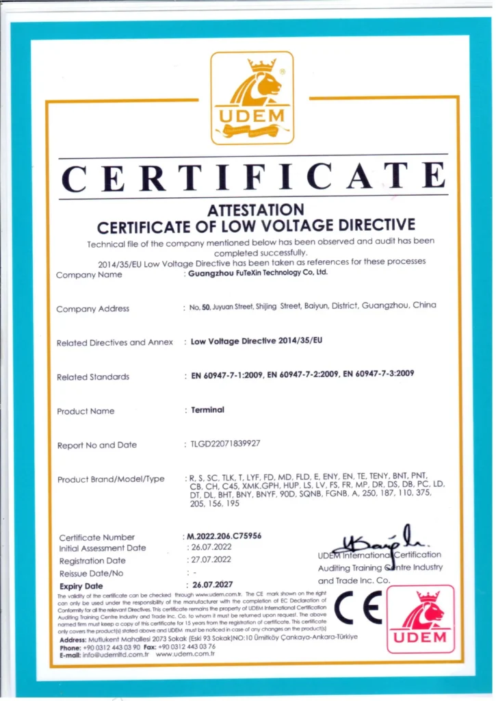
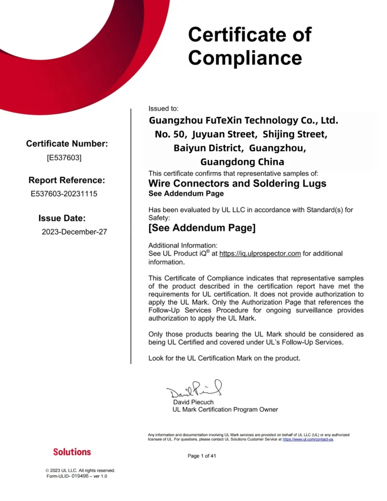
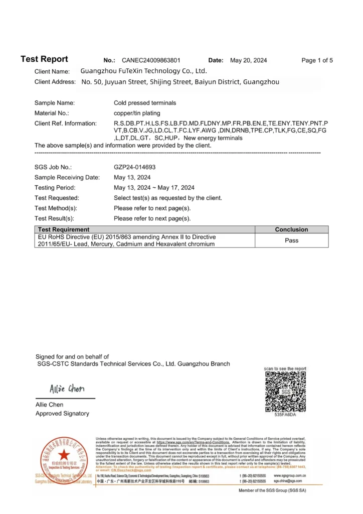
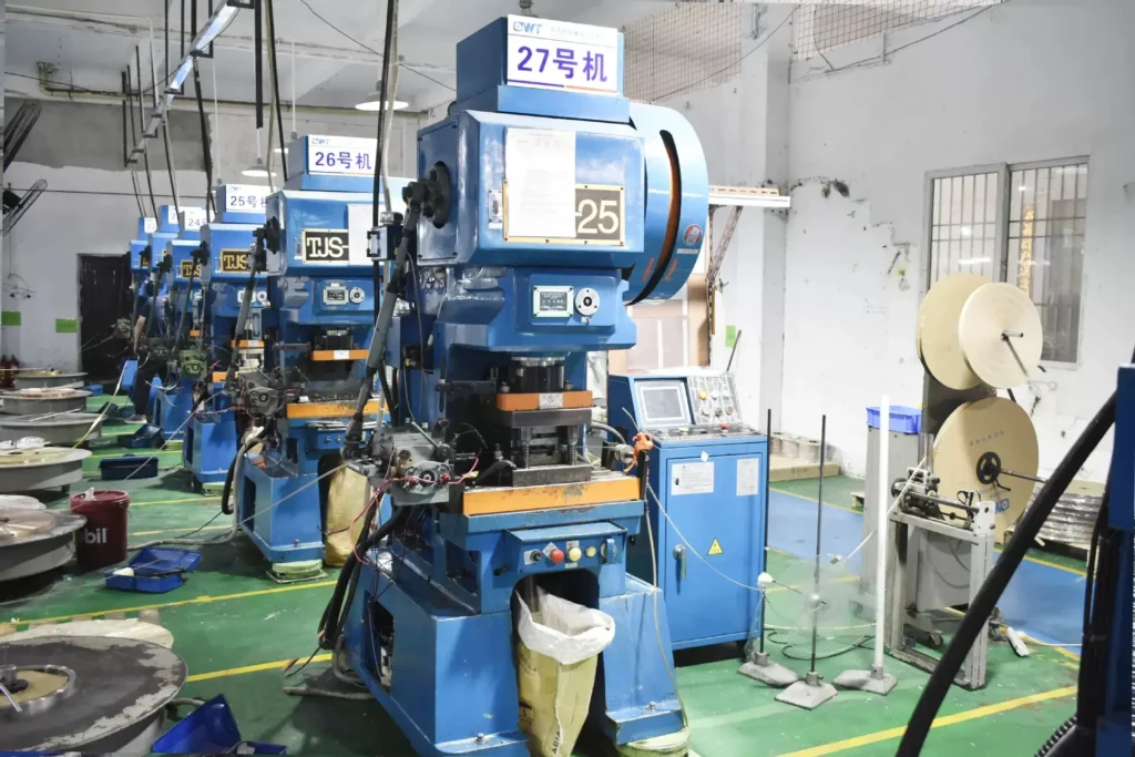
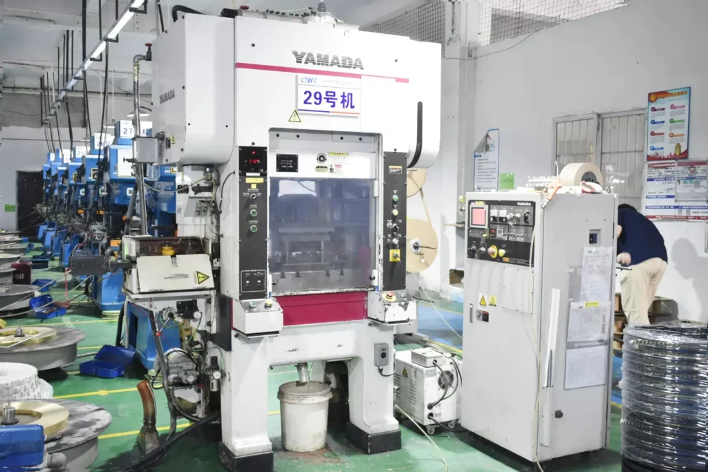
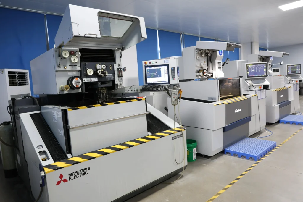
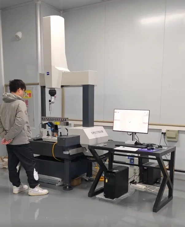
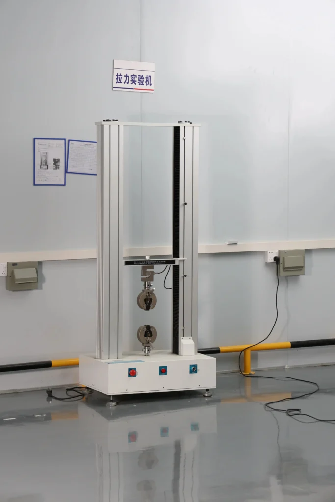
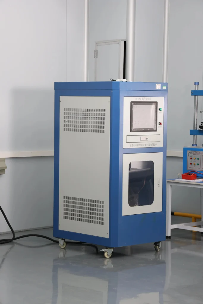
CE covers the full VoltixC terminal range, these splices included, under the Low Voltage Directive 2014/35/EU and the standards EN 60947-7-1, EN 60947-7-2 and EN 60947-7-3. VoltixC is UL certified; ask for the UL scope by part number with your enquiry. RoHS test report available (SGS): lead, mercury, cadmium and hexavalent chromium were tested on tin-plated copper terminal samples. The documents name Guangzhou FuTeXin Technology Co., Ltd., the company behind VoltixC, which runs a 1,200 m² factory in Guangzhou with 25 staff and 135 production machines. Certificate numbers and dates are not printed on this page.
Put these four questions on the splice enquiry, whichever maker it goes to:
The price of a copper butt splice order is set by the series, the conductor size mix, the quantity per size and any change you ask for to the standard part. Next to each driver, the table notes its effect on cost and what you can fix before quoting.
| Driver | Effect on cost | What you control |
|---|---|---|
| Series and joint type | A 1000 kcmil compression butt splice holds more copper than a BNT0.5 | Choose butt or parallel and the series from the model tables |
| Conductor size mix | Large kcmil sizes weigh more per piece than small AWG sizes | Group sizes you can standardize before you send the list |
| Quantity per size | Setup is spread over the pieces of each size | Send quantities per size, not one total |
| Plating and finish | Plating requests other than the listed finish add a process step | State tin-plated or bare copper on the enquiry |
| Marking, packing and private label | Custom bags, labels or printed marks add work per lot | Say whether standard packing is acceptable |
| Drawing-based change | A new barrel length or a reducing splice needs its own tooling | Send the drawing; tooling is confirmed per order |
| Documents | Certificate copies and material statements take time to prepare | List the documents you need at the enquiry stage |
Lead time, MOQ, warranty and payment are confirmed per order by email or the enquiry form. For samples, the fastest turnaround is 7 days; other dates are set in the quotation.
Send these details with your size list:
The reply to a size list names the matched model for each line, flags any line where the conductor size or strand class is unclear, and lists the fields still open, such as plating, die reference or packing. You confirm those fields before the quotation is final. A later order for the same list can quote the same model references, so the second enquiry is a copy of the first.
One size tool and three guides help you narrow the part before you write to VoltixC.
Look up conductor sizes in AWG, kcmil and mm² in the cable lug size chart, then carry the size into the model tables above.
The how to use butt connectors guide walks through stripping, inserting and crimping a butt splice.
The wire crimping guide covers die choice, strip length and pull checks for crimped joints.
The wire connector types guide places splices next to lugs, taps and insulated terminals.
A center stop, or wire stop, sets how far each conductor goes into the barrel. The BNT and DS / LS sheets do not show whether a stop is fitted, so VoltixC confirms it on the drawing per order. Where a splice has a wire stop, according to Panduit the first crimp goes near it, with later crimps working toward the wire entry. Follow the crimp order in the terminal maker’s instructions for the part you buy.
Use a butt splice when the two cables arrive from opposite directions and continue in one line: BNT from 26-22 AWG to 4/0 AWG, or DS / LS from 8 AWG to 1000 kcmil. Use a parallel splice when both conductors arrive from the same side and end together: PNT, in 13 sizes from 26-22 AWG to 4/0 AWG. Parallel splices above 4/0 AWG are not listed.
Yes, on a separate page. Vinyl and nylon insulated splices are on the insulated butt connectors page, and sleeved heat-shrink parts are covered on the heat-shrink splice page. This page lists bare copper parts only.
The difference is the sleeve. An insulated butt connector has a vinyl or nylon sleeve fitted over the barrel at the factory. A non-insulated butt connector is the bare copper barrel, which on this page runs from 26-22 AWG to 1000 kcmil and is covered on site with heat-shrink sleeving or tape after crimping.
For 4 AWG, the listed parts are BNT22 and DS0429, or the longer LS0429; for 6 AWG, BNT14 and LS0624 or DS0624-50. If the two 4 AWG or 6 AWG conductors lie side by side, PNT22 and PNT14 are the parallel versions.
The smallest are BNT0.5 and PNT0.5, listed for 26-22 AWG (0.2-0.5 mm²). The largest are DS1152 and LS1152 for 1000 kcmil. The sheets hold 126 part numbers: 100 DS / LS, 13 BNT and 13 PNT.
Not automatically. A question on the Electrician Talk forum asks whether crimp sleeves are universal across tool brands. Die codes belong to each maker’s chart. The DS / LS sheet prints a die color and code for each part, such as brown and 33 for DS0233 at 2 AWG; the BNT sheet names no die. Send your tool and die model with the size list, and VoltixC confirms the match for each barrel per order.
No. According to Panduit, installers should never use a copper connector on aluminum wire. All three series on this page are copper, so an aluminum splice needs a separate enquiry with both conductor types stated.
The crimp count comes from the die chart for the exact part, not from the marks on the barrel. According to Panduit, barrel stripes help space crimps evenly but do not designate the number of crimps. The DS / LS sheet prints the die code but no crimp count, so VoltixC confirms crimps for each size per order.
No. The tables repeat the supplier specification sheets, and VoltixC has not re-tested each value. Crimp counts, and plating on DS / LS parts, are not on the sheets and are confirmed per order; for your own crimp trial, the fastest sampling is 7 days.
List each size with its unit, the joint type and the quantity; the reply matches each line to a row of the model tables. Drawings and cable photos go by email to hugo@voltixconnect.com. For the rest of the copper range, see the cable lugs overview.
Ask a VoltixC Engineer