VOLTIXC / ENQUIRY
Request a Quote
Tell us what you need and we will review your enquiry.

By VoltixC Engineering Team · Last updated: 2026-09-28
Fast answer: To use a butt connector, pick one whose colour band matches the wire gauge, strip each wire to the barrel length, push each end in until it meets the centre stop, crimp both sides with a ratchet tool, then pull-test and check the insulation. Heavier cables above the insulated range need a copper butt splice instead.
A butt connector is a short copper barrel, bare or inside an insulating sleeve, that joins two wire ends in a straight line. Each wire enters from its own end and stops at a divider in the middle, and one crimp on each half holds it there. Electricians also call the part a butt splice; it is how to connect two wires with a connector when both ends meet head on. The bare copper versions VoltixC makes for heavier cable are on its non insulated butt connectors page, from 26-22 AWG up to 1000 kcmil.
This guide covers insulated butt splices from 22-16 AWG to 2 AWG, the parallel, step-down and closed-end parts people mix them up with, and the switch to bare copper on heavy cable. Tool brands and pull-force figures are left out, since VoltixC makes connectors rather than crimpers and ran no tests for this page.
The wire gauge has to sit inside the band printed on the connector, each stripped end has to fill half the barrel, and each side takes one crimp of its own.
| Check | What to confirm | Covered in |
|---|---|---|
| Connector type | A butt splice for two wires meeting end to end; a parallel, step-down or closed-end part for any other layout | Which connector you need |
| Wire band | VoltixC BV vinyl-insulated butt splices are listed in 22-16, 16-14, 14-12, 12-10, 8, 6, 4 and 2 AWG bands, and your wire has to fall inside one of them | Size, colour and insulation |
| Sleeve colour | The colour stands for a wire range on one maker’s chart; according to Waytek, insulated terminal sleeves are colour-coded by wire gauge: red 22–18, blue 16–14 and yellow 12–10 AWG | Size, colour and insulation |
| Standard scope for small splices | UL 486C covers splicing connectors intended to hold two or more conductors and for use with 6 AWG or smaller conductors, and tool-applied crimp connectors are listed among its examples | Heavier cables |
| Copper range in that standard | UL 486C lists copper conductor ranges of 30–10 AWG solid and 30–6 AWG stranded for splicing wire connectors | Size, colour and insulation |
| Strip length | Half the barrel for each wire, taken from the connector in your hand | Step by step |
| Centre stop | Present on a butt splice; each wire stops at the middle | What a butt connector is |
| Crimps per side | One on each end, never one crimp across the middle | Step by step |
| Upper wire size | Past the largest insulated band, change to a copper butt splice; according to CSA Group, the scope of C22.2 No. 65 includes splicing wire connectors intended for use with conductors of 4 AWG (21.2 mm²) or larger | Heavier cables |
Source: VoltixC supplier data as listed; not individually re-tested; other rows from the sources cited below.
Naming UL 486C and CSA Group here describes what those standards cover. It says nothing about a certificate for any VoltixC part. When a row fails, swap the connector before any insulation comes off.
| Also asked as | Short answer | Covered in |
|---|---|---|
| How to use a butt connector; how to use a butt splice; how to use butt splice; how to use splice connectors | Strip each wire to half the barrel, push it to the centre stop, crimp each half once, then pull-test | Step by step |
| How to crimp butt connectors; how to crimp a butt connector; crimping butt splice | One full ratchet stroke on each half, in the die nest marked for the sleeve’s band | Tools; step by step |
| What is a butt splice; what is butt splice | Another name for a butt connector: a barrel with a centre stop that joins two wire ends in line | What a butt connector is |
| How to crimp two wires together | Same size, end to end: a butt splice with one crimp per side; side by side: a parallel splice | Which connector you need |
A butt connector, also sold as a butt splice, is a metal barrel that holds two wire ends nose to nose, and its centre stop keeps each wire in its own half so both crimps land on copper.
| Problem | What to do | Check |
|---|---|---|
| A wire run is too short, or a conductor has been cut | Join the two ends in one butt connector of the matching band | Both ends sit in the same barrel, one from each side |
| You cannot feel where one half ends | Push the wire in slowly until it meets resistance. On 3M’s parts, the vinyl-insulated seamless butt connectors have chamfered barrel ends for easier wire insertion and a built-in wire stop for correct positioning | The wire stops at the midpoint of the barrel |
| The second wire will not go in far enough | Pull the first wire back to the stop, or start again with a new connector | Both copper ends meet at the stop |
| The joint sits dry inside a panel or enclosure | Use a vinyl-insulated butt connector, which gives basic insulation over the crimp | The sleeve comes out of the tool with no crack |
| The wire flexes or gets pulled near the joint | Look at nylon-insulated versions; some add a metal grip under the nylon that takes a second, lighter crimp on the wire insulation | The insulation stays held when you bend the wire |
| Moisture has to stay out | Use a heat-shrink crimp connector, which closes a sleeve over the crimp with heat | The sleeve is shrunk tight at both ends |
| Two wires come in from the same side | Switch to a parallel splice or a closed-end connector | The comparison table in the next section lists both |
| The two wires are different sizes | Switch to a step-down butt splice | Each side’s band covers its own wire |
A butt connector joins wires and does not end one; a wire that stops at a stud or a screw needs a ring or spade terminal. VoltixC’s heat-shrink crimp range is not on the current list, so ask before you specify it.
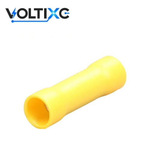
Two same-size wires meeting end to end take a butt splice; the parallel splice, step-down butt splice and closed-end connector cover side-by-side entry, unequal sizes and capped bundles.
| Connector | How the wires go in | Internal stop | Best for | VoltixC page |
|---|---|---|---|---|
| Butt splice | One wire from each end, same band on both sides | Yes, at the centre | Extending or repairing a run in a straight line | BV vinyl-insulated on butt connectors; BNT bare copper on the non insulated page |
| Parallel splice | Both conductors from one side, lying next to each other | Not needed; the wires lie side by side | Two conductors that end at the same point | PNT series on the copper butt and parallel splices page |
| Step-down butt splice | A smaller wire, or more wires, on one side than on the other | Yes, at the centre | Joining unequal sizes or counts in line | Not a listed VoltixC series; shown for comparison |
| Closed-end connector | All wires twisted together and pushed into the one open end | Closed at the far end instead | Capping a bundle of wires, for example in a fixture box | CE series, nylon-insulated, on the butt connectors page |
| Point | What the data says | Source |
|---|---|---|
| Standard scope | UL 486C applies to single-polarity, hand- or tool-applied splicing wire and cable connectors for copper, aluminum or copper-clad aluminum conductors under CSA C22.1, NFPA 70 or NOM-001-SEDE | UL Standards & Engagement, UL 486C store page |
| Closed-end: what it is | A crimp sleeve connector with a copper insert, used to splice copper conductors | 3M closed-end connector page |
| Closed-end: how it is rated | By copper wire combinations, such as 2 to 5 #22 or 2 or 3 #20 conductors | 3M S11-A data sheet |
| Closed-end: how it goes on | Strip all wires ½ inch, pre-twist the wires, insert them into the connector and crimp | 3M S11-A data sheet, installation section |
| Step-down: how the sides differ | A different colour stripe on each side, for example red for one 22–18 AWG wire and blue for two 22–18 AWG wires | Pacer, step-down butt splices product page |
| More than one wire per side | Wires can be combined in PIDG terminals and splices as long as total circular mil area and insulation diameter stay within specification | TE Connectivity, PIDG brand page |
Source: connector layouts from the VoltixC product pages linked above (supplier data as listed); other rows from the sources named in each row; the Pacer and 3M figures describe their own parts only.
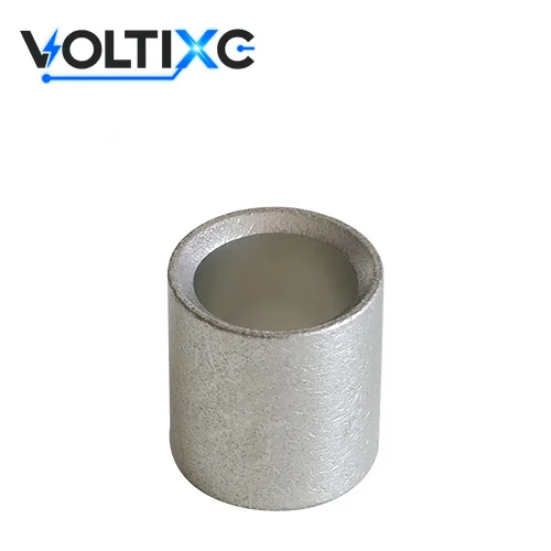
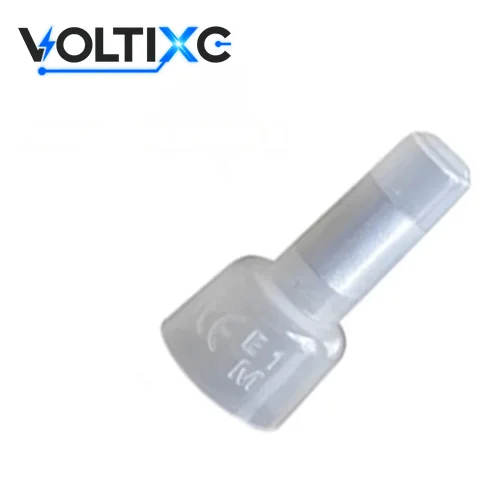
Pick the band that contains the conductor size printed on the cable, and pick vinyl, nylon or heat-shrink for the place the joint will sit.
| Input | Where to get it | What it decides |
|---|---|---|
| Conductor size (AWG) | Printed on the cable jacket; Wiltronics advises that installers should size a connector from the conductor size printed on the cable, not from the cable’s outside diameter alone | The connector band |
| Insulation outside diameter | A caliper on the jacket; TE Connectivity’s guide says insulation outside diameters vary among wires with the same AWG size, so the insulation barrel must accommodate the wire’s outside diameter and the crimp range must match it | Whether the sleeve closes on the jacket |
| Band printed on the connector | The sleeve itself or the pack label | The die nest on the crimping tool |
| Sleeve colour | The chart from the maker of that connector; Wiltronics notes that colour-coded conductor ranges on insulated terminals can differ between manufacturers and connector systems, so the specific terminal’s data should be checked | A quick visual check against that chart only |
| Where the joint sits | Dry panel, vehicle loom, boat, damp or outdoor location | Vinyl, nylon or heat-shrink sleeve |
| Wire on the job | VoltixC BV band to start from | Check before crimping |
|---|---|---|
| 22, 20 or 18 AWG | 22-16 AWG | A thin wire in the smallest band still needs the sleeve to grip its jacket |
| 16 AWG | 22-16 or 16-14 AWG | 16 AWG sits on the edge of two bands; the jacket diameter picks one |
| 14 AWG | 16-14 or 14-12 AWG | The same edge case; measure the jacket |
| 12 AWG | 14-12 or 12-10 AWG | The same edge case again |
| 10 AWG | 12-10 AWG | Solid or stranded, the band has to cover the wire as printed |
| 8 or 6 AWG | The 8 or 6 AWG size | Single-size parts, so the wire has to match exactly |
| 4 or 2 AWG | The 4 or 2 AWG size | The heaviest insulated sizes on the list; above 2 AWG, read the heavier-cable section |
Source: VoltixC supplier data as listed (BV series; not individually re-tested).
| Sleeve | What it gives | Pick it when |
|---|---|---|
| Vinyl (PVC) | A basic layer to insulate the crimp | The joint sits dry and protected; VoltixC’s BV butt splices are vinyl |
| Nylon | Insulation over the crimp, and on some versions a metal grip that takes a second crimp on the wire jacket | The wire flexes or is handled near the joint; VoltixC’s CE closed-end connectors are listed with nylon |
| Heat-shrink | Heat-shrink tubing over the crimp, shrunk with a heat gun after crimping | Moisture has to stay out; ask the maker whether the sleeve has an adhesive lining. Heat-shrink parts are not on the current VoltixC list, so ask before you specify |
Colour check: Waytek’s chart codes insulated terminal sleeves by wire gauge as red 22–18, blue 16–14 and yellow 12–10 AWG. VoltixC lists its smallest BV band as 22-16 AWG, so read the band printed on the part.
For a wire sized in mm², convert it with the cable lug size chart before picking the band.
A wire stripper and a ratchet crimper with a die nest for the connector’s band do the job, plus a heat gun for heat-shrink butt connectors.
| Tool | What it does | What to check |
|---|---|---|
| Wire stripper | Takes the insulation off to half the barrel length | The strands come out whole, with no nick in the copper |
| Ratchet crimping tool with insulated-terminal dies | Closes each half of the barrel through a full stroke and releases only at the end of it. According to Wiltronics, crimp tools for pre-insulated terminals produce a different crimp profile from tools for uninsulated lugs, bootlace ferrules and other connector systems | The die is marked for insulated splices, not for bare lugs or ferrules |
| Colour-coded die nests | Match the nest to the sleeve band. TE Connectivity colour-codes its PIDG insulation sleeves and the corresponding tooling by wire size | Nest marking and sleeve band agree on the same maker’s chart |
| Heat gun | Shrinks a heat-shrink sleeve once the crimp is done | The sleeve is shrunk evenly all the way round |
| Ordinary pliers | Nothing on this job: ordinary pliers should not be used on standard pre-insulated butt, ring, fork or spade terminals unless the maker states they are suitable (Wiltronics) | The joint waits until the right tool is at hand |
| Any crimping setup | TE Connectivity lists four conditions for a quality crimp: correct tooling for the terminal and wire, the correct terminal for the application, properly prepared wire, and a trained operator | Tool, connector and stripped wire all match before the first crimp |
| Boat wiring | On a boat, solderless crimp-on connectors must be attached with a crimping tool designed for the connector under ABYC E-11.14.3.8, as West Marine sets out | The tool is the one made for that connector |
Electricians on trade forums ask whether crimp sleeves are universal across crimper brands; checking the die against the sleeve maker’s chart answers it for your parts. VoltixC sells connectors and no crimp tools, so no brand or model is named here.
Each wire gets stripped to half the barrel, pushed to the centre stop and crimped once on its own side, and a pull test closes the job.
Strip the first wire to half the length of the connector barrel.
Held against the sleeve, its bare copper reaches the middle and every strand is whole.
Push the stripped end into one side of the connector until it stops at the centre.
You should see no bare copper outside the sleeve.
With the first wire seated, crimp that half once in the die nest marked for the connector’s band; then strip, insert and crimp the second wire from the other end.
There are now two indents, each on its own half.
Last, pull each wire firmly by hand and look the sleeve over.
A wire that moves or a split sleeve means the connector comes out and the joint is made again.
| Step | What the source says | Source |
|---|---|---|
| Step 1: clean strip | Insulation must be removed to the proper length cleanly, without nicking or breaking wire strands; the manual illustrates acceptable and rejected strip examples | TE Connectivity, Guide to Crimping (strip examples) |
| Step 1: strip length | Strip enough insulation for the conductor to fill the terminal’s wire barrel without leaving unnecessary bare wire exposed behind the connector | Wiltronics crimping guide |
| Step 2: insert | For a butt splice, each wire is prepared to fit within its own half of the connector | Wiltronics |
| Step 3: crimp | The wire barrel provides the electrical and mechanical connection, while the insulation barrel provides strain relief and requires a more relaxed crimp without providing an electrical connection | TE Connectivity, Guide to Crimping |
Before the first cut, hold the connector beside the wire and mark the halfway point on the insulation with a pen; strip to that mark. On a stranded wire, a light twist in the existing lay keeps stray strands out of the way as the end goes in.
Tip: Crimp the first side and tug it before the second wire goes in. A loose first side is easier to redo while the other end of the connector is still empty.
A good butt connector crimp shows one indent on each half, leaves the sleeve unbroken and holds when you pull each wire; a joint that fails any of those gets cut out and replaced.
| Problem | What to do | Check |
|---|---|---|
| A wire moves or pulls out under a steady pull | Cut the connector off and crimp a new one; Wiltronics says a crimp that moves or pulls out in a steady in-line pull test should be cut off and redone with a new terminal, and crimped terminals should not be reused | Both wires hold under a firm in-line pull |
| One crimp was placed across the middle to catch both wires | Replace the connector and crimp each side once. According to Wiltronics, both sides of a butt splice should not be crimped with one off-centre compression | Two indents, one per half |
| The strip exposes bare copper between the sleeve and the wire insulation | Cut it out and strip the next wire shorter | No copper visible at either end |
| The wire end stopped short of the centre | Cut it out and push the next wire all the way to the stop before crimping | The copper tip sits at the stop |
| The sleeve split or flattened in the tool | Crimp a new connector in the insulated-splice nest of the right band | The sleeve comes out whole |
| A meter shows continuity, so the joint looks fine | Pull-test it anyway: in Wiltronics’ guidance, electrical continuity alone does not prove that a crimp is mechanically secure | The pull test passes as well as the meter |
| A heat-shrink sleeve is wrinkled or shrunk on one side only | Heat it again, evenly; 3M states that heat-shrink products must be heated uniformly all the way around to achieve a good installation | The sleeve is tight on every side |
| Heat-shrink is covering a loose crimp | Cut the joint out and crimp again before any heat goes on; Wiltronics adds that heat-shrinking a sleeve must not be used to conceal or compensate for a loose crimp | The pull test is done before shrinking |
| A batch of joints has to come out the same | Keep the process controlled; a NASA technical report states that reliable crimped electrical contacts require strict process controls and continuous pull-force process verification | Pass values come from your standard or the connector maker |
This guide gives no pull-force values; your standard or the connector maker sets them. A joint that survives the pull but shows a split sleeve still gets replaced.
Caution: A second squeeze on a failed butt connector leaves the fault in place. Cut the connector out, strip fresh ends and start again with a new part.
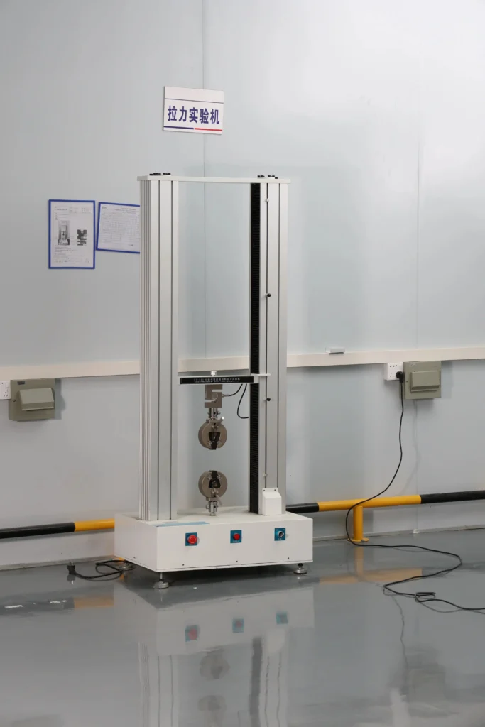
Move to a copper butt splice once the cable is heavier than the largest insulated band you can get, which is 2 AWG on VoltixC’s BV list, and crimp it with the die its maker specifies.
| Wire on the job | What to use | Where on VoltixC |
|---|---|---|
| 22-16 to 2 AWG, insulation wanted | BV vinyl-insulated butt splice in the matching band | insulated butt splices |
| 26-22 AWG to 4/0 AWG, bare copper | BNT copper butt splice | non insulated butt connectors page |
| 8 AWG to 4/0 AWG, and 250 to 1000 kcmil | Copper compression butt splice | copper compression splices |
| Two conductors side by side, 26-22 AWG to 4/0 AWG | PNT parallel splice | non insulated butt connectors page |
| Aluminium conductor | A connector marked for aluminium | Not on the current list; ask before you specify |
Source: VoltixC supplier data as listed (BV, BNT, PNT and compression butt splice series; not individually re-tested).
A bare copper splice carries no sleeve, so any insulation over it goes on after the crimp and follows the installation rules for the job. Die size and crimp count for each heavy splice come from its maker; this guide gives neither.
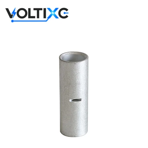
Insulated butt splices from 22-16 to 2 AWG are on VoltixC’s butt connectors page, bare copper butt and parallel splices up to 1000 kcmil are on the non insulated butt connectors page, and a bulk quote starts with the wire gauge, splice type and quantity.
| What you need | Go to | Send with the enquiry |
|---|---|---|
| Vinyl-insulated butt splices, 22-16 to 2 AWG | insulated butt connectors | The AWG band and the quantity for each band |
| Closed-end connectors, 22-16 to 8 AWG | The same butt connectors page | The wire count and gauges going into each cap |
| Bare copper butt splices and PNT parallel splices | bare copper splice range | Conductor size in AWG or kcmil, and conductor material |
| Sealed crimp joints | heat shrink butt connectors | Sizes and quantity; the range is not on the current list, so ask before you specify |
| A joint made with solder and heat instead of a crimp | solder seal connectors | Wire size and quantity |
| Ring, spade, quick-disconnect and other insulated terminals | crimp connectors | Terminal type, wire size and stud or tab size |
| AWG and mm² side by side | AWG to mm² size chart | — |
| Crimping other terminal types | crimping guide for other terminals | — |
The quote form takes the product line, conductor size and quantity, and its message box carries the rest: splice type, insulation, conductor material, any drawing reference. The form has no upload field, so drawings or photos follow by email to hugo@voltixconnect.com once the form is in. Packing, samples and delivery terms are agreed per order in that reply.
It sets how far each wire goes in, so each conductor fills its own half and both crimps land on copper. On 3M’s vinyl-insulated seamless butt connectors, a built-in wire stop gives correct positioning, and chamfered barrel ends make wire insertion easier. Without the stop, one wire could cross the middle and leave the other half short.
When both conductors have to enter from the same side and lie next to each other. A butt connector stays the choice for two wires of one size meeting end to end. If you plan to put more than one wire into a side, TE Connectivity allows wires to be combined in PIDG terminals and splices as long as total circular mil area and insulation diameter stay within specification.
They point you to a wire range and the die nest that goes with it, on that maker’s chart only. The range behind each colour varies by maker, so read the band printed on the connector and match the die to it.
A ratchet crimping tool with a die for insulated splices in the connector’s band. According to TE Connectivity, a quality crimp requires correct tooling for the terminal and wire, the correct terminal for the application, properly prepared wire, and a trained operator. The wire stripper does the preparation, and a heat gun is only needed for heat-shrink sleeves.
Two indents, one on each half, an unbroken sleeve and two wires that hold under a firm pull. Test each side on its own. On a heat-shrink type, 3M’s instruction that heat-shrink products must be heated uniformly all the way around to achieve a good installation adds one more check: a sleeve tight on every side.
Once the wire is heavier than the largest insulated size you can get, which is 2 AWG on VoltixC’s BV list. The bare copper splices on the non insulated butt connectors page run from 26-22 AWG up to 1000 kcmil, and each is crimped with the die its maker specifies.
Either the 22-16 AWG or the 16-14 AWG band, since 16 AWG sits at the edge of both on VoltixC’s BV list. Measure the jacket and take the band whose insulation barrel closes on it without crushing it, because insulation outside diameters vary among wires with the same AWG size (TE Connectivity). In the Waytek colour example, 16 AWG falls in the blue 16–14 band, and another maker’s blue can cover a different range.
How this guide was written: it follows a butt-connector job from choosing the part to checking the joint. The sources are TE Connectivity’s crimping guide and PIDG page, 3M product pages and data sheets, Wiltronics, Waytek, Pacer, Panduit, West Marine, the UL Standards & Engagement and CSA Group standards stores, and a NASA technical report. VoltixC ran no tests for this guide and gives no pull-force figures. Wire bands come from VoltixC supplier data as listed and have not each been re-tested.
VoltixC is the brand of Guangzhou FuTeXin Technology Co., Ltd. It makes the insulated butt splices, closed-end connectors and bare copper splices this guide describes; crimp tools are outside its range.