VOLTIXC / ENQUIRY
Request a Quote
Tell us what you need and we will review your enquiry.

By VoltixC Engineering Team · Last updated: 2026-09-28
Fast answer: Female spade connector sizes start with tab width and thickness, such as 0.187 or 0.250 inch, and then the wire range the barrel accepts. Match male and female parts on the same tab size, choose straight or flag shape for the layout, and pick vinyl, nylon or fully insulated construction for the crimp and environment.
A technician replacing a thermostat pulls the old receptacle off a flat tab and needs a new one for that same tab. Calipers go on the tab before anyone looks at the wire. After the tab come the wire band for the barrel and the clearance in front of the tab, which decides between a straight and a flag body; the sleeve depends on the job. VoltixC lists 52 quick disconnect terminals in six series, each offered in 22-16, 16-14 and 12-10 AWG, within its crimp connectors range.
Inch and millimetre figures here come from the UL 310 and IEC 61210 scope summaries and from Burndy’s data sheet, with the source named in each table. For its six series, the VoltixC supplier specification sheets print the mating tab, wire band, sleeve colour and body metal of every part number, and the VoltixC tables below are built from them.
Two numbers from the male tab define the fit, its width and its thickness, and the wire band and the sleeve are chosen after them.
| Spec | What to confirm | Working value |
|---|---|---|
| Tab width | Nominal width of the male tab on the device | UL 310 applies to quick-connect terminals, both connectors and tabs, with nominal widths of 2.8, 3.2, 4.8, 5.2 and 6.3 mm (0.110, 0.125, 0.187, 0.205 and 0.250 in) |
| Tab thickness | Thickness of the same tab, read across its edge | Burndy’s QP-F listing shows NEMA tab sizes of 0.11 × 0.02, 0.19 × 0.02, 0.25 × 0.03 and 0.38 × 0.05 in (width × thickness), and marks the 0.38 in items ‘Not cULus’ |
| Metric tab family | Tab width stated in mm on a European drawing | IEC 61210 applies to non-insulated flat quick-connect terminations with a male tab of 2.8, 4.8, 6.3 or 9.5 mm, with hole or dimple detents, and a mating female connector |
| Wire range in AWG | Conductor band that the barrel accepts | UL 310 requirements apply to quick-connect terminals for one or two 26–10 AWG copper conductors and do not apply to terminals for aluminum conductors |
| Wire range in mm² | Cross-section and conductor build | IEC 61210 covers copper conductors up to 6 mm² flexible or rigid stranded, or up to 2.5 mm² rigid solid, excludes aluminium, and limits rated voltage to 1,000 V AC / 1,500 V DC |
| VoltixC wire bands | Band on the item you order | 22-16, 16-14 and 12-10 AWG (0.5-1.5, 1.5-2.5 and 4-6 mm²) in each of the six series |
| Gender and shape | Male tab or female receptacle; straight or flag | FDD, FDFD and FDFN straight female; FLDNY flag female; MDD and MDFN male |
| VoltixC tab sizes | Mating tab printed for each part number | 2.8 to 9.4 mm wide and 0.5, 0.8 or 1.2 mm thick, nine sizes across 52 part numbers |
| Sleeve | Vinyl, nylon or fully insulated | PVC (vinyl) on FDD, FDFD and MDD; nylon on FDFN, FLDNY and MDFN |
| Body and plating | Base metal and finish | Tin-plated copper on FDD; tin-plated brass on FDFD, FDFN, FLDNY, MDD and MDFN |
| Colour band | What the sleeve colour stands for | Colour ranges vary by maker; the VoltixC sheets are color-coded red for 22-16 AWG, blue for 16-14 AWG and yellow for 12-10 AWG |
| Contact wear in tests | How a lab decides a joint has worn out | One fretting study measured the time and cycles needed to reach a 100 mΩ resistance threshold, a research threshold and not a standard limit |
Source: VoltixC rows per supplier specification sheet, not individually re-tested; other rows from the sources cited below.
Put the width and the thickness on one line as a pair, then the wire band, and only after that a series name; the item tables further down follow the same order.
| Also asked as | Short answer | Covered in |
|---|---|---|
| female quick disconnect terminal sizes; female disconnect terminal sizes; female spade terminal sizes | The same question as female spade connector sizes: the width and thickness of the mating tab first, then the wire band | Tab width and thickness section |
| quick disconnect terminal sizes; electrical blade connector sizes | The blade is the male tab, and its width and thickness are the size; each receptacle is made for one pair | Tab width and thickness section |
| male spade connector sizes | The same pair, read on the male part; VoltixC MDD and MDFN tabs run from 2.8 to 6.35 mm wide on the supplier sheets | VoltixC tab chart and series list |
| quick disconnect terminal size chart; female spade connector size chart | The VoltixC chart lists nine tab sizes, 2.8 to 9.4 mm wide, with the series and wire bands made for each | VoltixC tab chart |
| common sizes of spade terminals | On the VoltixC sheets, 6.35 mm is the one tab width offered in all six series | VoltixC tab chart |
| 16-14 gauge spade connector sizes | 16-14 AWG (1.5-2.5 mm², blue sleeve on the VoltixC sheets) comes with tabs from 2.8 to 9.4 mm wide | Wire gauge and colour section |
| color-coded spade connectors | The colour marks the wire band, not the tab, and other makers’ colour bands can differ | Wire gauge and colour section |
| how to insulate a spade connector | Choose a PVC (vinyl) or nylon sleeve, or a fully insulated body that also covers the mating point | Insulation section |
| spade connectors for automotive wiring | Tab sizes are read the same way; automotive harness terminal systems are outside the VoltixC list, so ask before you specify | Not covered here |
A quick disconnect is a crimp joint in two halves, a flat male tab and a female receptacle that slides onto it, so a wire can be unplugged and plugged back in without tools.
| Problem | What to do | Check |
|---|---|---|
| The two halves look alike in a mixed bag | Look at the front end. According to Burndy, a female quick disconnect has a receptacle front end that slides onto and off a male blade | The part with the rolled, open front is the female |
| A catalogue says slip-on, fast-on, push-on or blade | Read these as names for the same tab-and-receptacle family and ask for the tab size behind the name | The quotation gives a width and a thickness, not only a name |
| The device has a screw or a terminal strip, not a tab | Use a fork or spade that clamps under the screw head, from the insulated spade terminals range | A screw head sits where the joint goes |
| The device has a threaded stud | Size a ring terminal with the ring terminal lookup tool | The stud diameter is on the drawing |
| Two loose wire ends meet in line | Join them with a pin and socket; the crimp routine is in the bullet connector crimping guide | Neither end is fixed to a component |
| The joint will be opened for service | Keep the quick disconnect, since the receptacle pulls off the tab by hand | The replacement part plugs onto the same tab |
| The tab is punched into a switch, relay or heater | Measure that fixed tab before you choose a receptacle | Width and thickness are written on the order line |
Spade terminal and female spade connector sound alike but fit different hardware, and the naming overlap is sorted out in spade connector types. A quick disconnect carries a wire to a flat tab; the sections below size that tab.
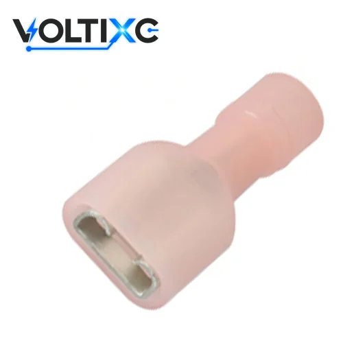
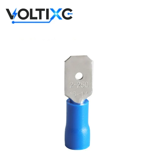
The receptacle follows the tab it mates with, and UL 310 names five nominal widths: 2.8, 3.2, 4.8, 5.2 and 6.3 mm, or 0.110, 0.125, 0.187, 0.205 and 0.250 in.
| Tab width (in) | Tab width (mm) | Thickness in Burndy’s listing | Named in |
|---|---|---|---|
| 0.110 | 2.8 | 0.02 in (about 0.5 mm), listed as 0.11 × 0.02 | UL 310; IEC 61210; Burndy QP-F |
| 0.125 | 3.2 | Not in that listing | UL 310 |
| 0.187 | 4.8 | 0.02 in (about 0.5 mm), listed as 0.19 × 0.02 | UL 310; IEC 61210; Burndy QP-F |
| 0.205 | 5.2 | Not in that listing | UL 310 |
| 0.250 | 6.3 | 0.03 in (about 0.8 mm), listed as 0.25 × 0.03 | UL 310; IEC 61210; Burndy QP-F |
| Not stated | 9.5 | Not stated | IEC 61210 |
| 0.38 | Not stated | 0.05 in (about 1.3 mm); Burndy marks these items ‘Not cULus’ | Burndy QP-F |
Source: UL 310 and IEC 61210 scope summaries and Burndy’s QP-F listing; the inch-to-mm pairs are as UL 310 gives them, and thickness in mm is converted and rounded here.
| Mating tab width (mm) | Mating tab thickness (mm) | Part-number suffix | Female series and wire bands (AWG) | Male series and wire bands (AWG) | Part numbers |
|---|---|---|---|---|---|
| 2.8 | 0.5 | -110 | FDD 22-16, 16-14, 12-10; FDFD 22-16, 16-14 | MDD 22-16 | 6 |
| 2.8 | 0.8 | -110 | FDD 22-16, 16-14, 12-10; FDFD 22-16, 16-14 | MDD 22-16 | 6 |
| 4.75 | 0.5 | -187 | FDD 22-16, 16-14, 12-10; FDFD 22-16, 16-14 | MDD 22-16, 16-14 | 7 |
| 4.75 | 0.8 | -187 | FDD 22-16, 16-14, 12-10; FDFD 22-16, 16-14 | MDD 22-16, 16-14 | 7 |
| 5.2 | 0.5 | -205 | FDD 22-16, 16-14 | — | 2 |
| 5.2 | 0.8 | -205 | FDD 22-16, 16-14 | — | 2 |
| 6.35 | 0.8 | -250 (FDFN, MDFN print no suffix) | FDD 22-16, 16-14, 12-10; FDFD 22-16, 16-14, 12-10; FDFN 22-16, 16-14, 12-10; FLDNY 22-16, 16-14, 12-10 | MDD 22-16, 16-14, 12-10; MDFN 22-16, 16-14, 12-10 | 18 |
| 8.0 | 0.8 | -312 | FDD 22-16, 16-14 | — | 2 |
| 9.4 | 1.2 | -375 | FDD 16-14, 12-10 | — | 2 |
Source: VoltixC supplier specification sheets, 52 part numbers, each printed with its mating tab size; not individually re-tested.
Spec note: Put width and thickness on the order line as one pair, in the unit your drawing uses; a width with no thickness leaves half of the fit open.
Calipers across the flat face give the width, and a micrometer or calipers across the edge give the thickness. The VoltixC chart gives the same two numbers for each part number, taken from the supplier sheets.
Straight receptacles and male tabs cover open panels, a flag receptacle turns the wire through 90° for tight spots, a piggyback adds a second tab, and locking or stud-mount designs hold the joint or the tab in place.
On a crowded appliance control board, the space in front of each tab decides the body. Where a lid or a relay sits close to the tab, the wire has to leave sideways, and a flag receptacle does that; with room to spare, a straight one goes on.
| Shape | Gender | Wire exit | Extra function | VoltixC series |
|---|---|---|---|---|
| Straight receptacle | Female | In line with the tab | Slides straight on | FDD (vinyl barrel sleeve), FDFD (vinyl, fully insulated), FDFN (nylon, fully insulated) |
| Flag receptacle | Female | 90° to the tab | Saves depth in front of the tab | FLDNY (nylon) |
| Male tab | Male | In line | Puts the tab on the harness side | MDD (vinyl barrel sleeve), MDFN (nylon, fully insulated) |
| Dimpled detent | Female | In line | Grips the tab; according to Burndy, a dimpled female socket detent on its quick disconnects ensures a firm grip on the tab | Detent style confirmed per order |
| Piggyback | Female, with a male tab on its back | In line | Takes a second connection on the same tab | Not on the current list; ask before you specify |
| Locking | Female, male or both | In line | A latch holds the two halves together | Not on the current list; ask before you specify |
| Stud-mount tab | Male | Set by the mounting | Fixes the tab to a stud or panel | Not on the current list; ask before you specify |
Source: shape descriptions are general; the detent row is Burndy’s QP-F listing; VoltixC series from supplier data as listed.
If the device already carries a piggyback or a locking tab, send a photo of it with the enquiry, because none of the six listed series copies those shapes. A flag part and a straight part of the same wire band take the same crimp; only the exit direction changes.
Tip: Before you choose flag or straight, hold a ruler in front of the tab and note the gap to the nearest lid or part; write that gap on the enquiry next to the tab size.
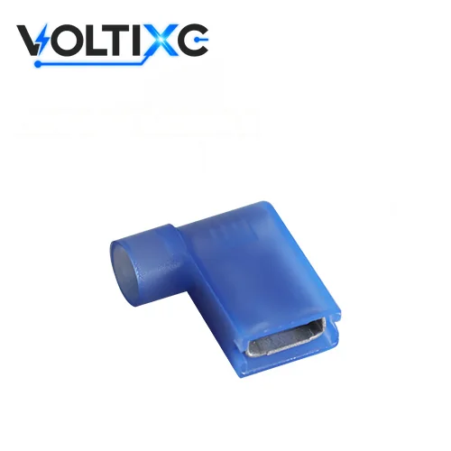
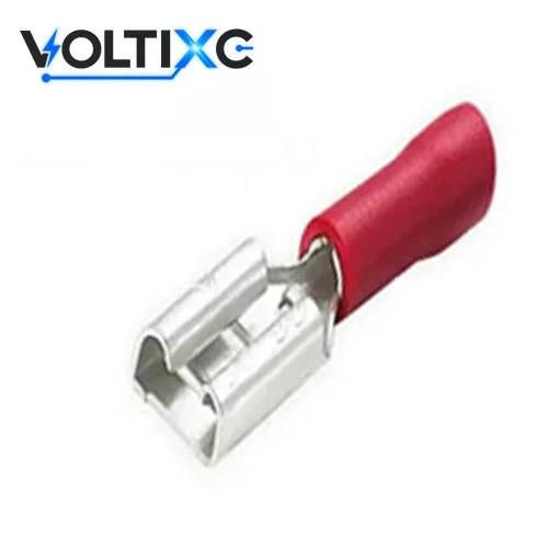
Count the crimp zones: nylon parts built for double crimping take two, and a single vinyl or bare barrel takes one.
A fully insulated part carries its sleeve over the receptacle too, so the mating point stays covered once the tab is in. VoltixC lists PVC (vinyl) on FDD, FDFD and MDD and nylon on FDFN, FLDNY and MDFN, and the crimp zones of each series are confirmed per order. The supplier sheets print 75 for the PVC series and 105 for the nylon series with no unit symbol, and no voltage rating for any of the six, so ask before you specify a rating.
| Insulation | Crimp zones | Covers the mating point | VoltixC series |
|---|---|---|---|
| Bare (non-insulated) | One, on the wire barrel | No | Not on the current list; ask before you specify |
| Vinyl barrel sleeve | One, through the sleeve | No; the receptacle or tab stays bare | FDD, MDD |
| Vinyl, fully insulated | Confirmed per order | Yes; the sleeve runs over the receptacle | FDFD |
| Nylon, fully insulated | Two where the part is built for double crimping; confirmed per order | Yes | FDFN, MDFN (how far the MDFN shroud reaches along the tab is confirmed per order) |
| Nylon flag | Confirmed per order | Coverage confirmed per order | FLDNY |
| Heat-shrink sleeve | Crimp, then heat the sleeve to insulate the joint | Sealed once shrunk | Not on the current list; ask before you specify |
| Point | What the data says | Source |
|---|---|---|
| Vinyl | Vinyl insulation is the most economical option and gives basic protection against accidental contact | Waytek |
| Nylon, double crimp | Many nylon-insulated terminals are designed for double crimping, which adds strain relief and tensile strength | Waytek |
| Insulation support sleeve | The copper insulation-support sleeve lets the wire bend in any direction without fraying the insulation or breaking the conductor | TE Connectivity, PIDG page |
| Heat shrink | Heat-shrink insulated terminals seal tightly when heated properly, giving moisture resistance and corrosion protection | Waytek |
| Bare barrel | Non-insulated terminals should only be used where no additional electrical protection is necessary | Waytek |
| One maker’s vinyl rating | Burndy’s vinyl-insulated female quick disconnects are tin-plated brass rated 600 V max and 105 °C max; the figures belong to Burndy’s parts | Burndy QP-F listing |
Source: Waytek, TE Connectivity and Burndy pages listed under References; none of them describes VoltixC parts.
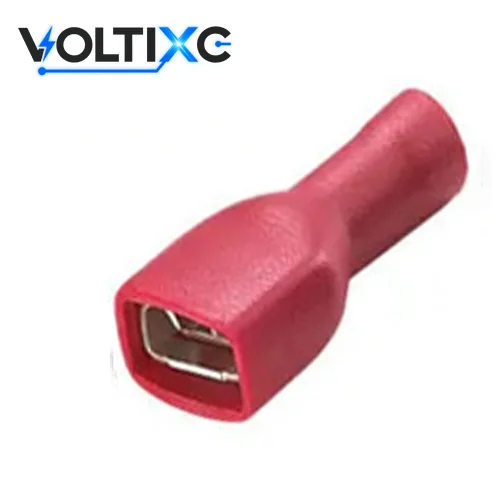

Pick the barrel by wire band and the receptacle by tab size; the sleeve colour only marks the band, and colour ranges vary by maker.
Every VoltixC series covers three bands, 22-16, 16-14 and 12-10 AWG, which the supplier sheets print as 0.5-1.5, 1.5-2.5 and 4-6 mm² with red, blue and yellow sleeves. Measure the jacket as well as the conductor, since the insulation grip closes on the jacket. Aluminium wire needs a terminal made for it; both scope summaries below leave it out.
| Point | What the data says | Source |
|---|---|---|
| UL 310 wire scope | UL 310 requirements apply to quick-connect terminals for one or two 26–10 AWG copper conductors and do not apply to terminals for aluminum conductors | ULSE, UL 310 listing |
| IEC 61210 wire scope | IEC 61210 covers copper conductors up to 6 mm² flexible or rigid stranded, or up to 2.5 mm² rigid solid, excludes aluminium, and limits rated voltage to 1,000 V AC / 1,500 V DC | IEC 61210 summary, iTeh Standards |
| Jacket diameter | Insulation outside diameters vary among wires with the same AWG size, so the insulation barrel must accommodate the wire’s outside diameter and the crimp range must match it | TE Connectivity, Guide to Crimping |
Source: the standards summaries and maker guide named in each row.
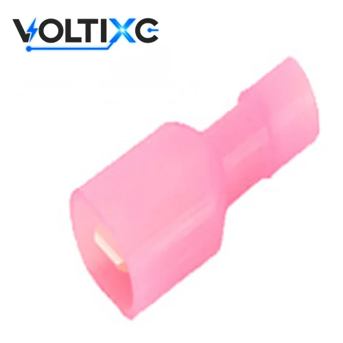
| Wire band (AWG) | mm² | Sleeve colour on the sheets | Female, straight | Female, flag | Male |
|---|---|---|---|---|---|
| 22-16 | 0.5-1.5 | Red | FDD1.25 (8 part numbers), FDFD1.25 (5 part numbers), FDFN1.25 | FLDNY1.25-250 | MDD1.25 (5 part numbers), MDFN1.25 |
| 16-14 | 1.5-2.5 | Blue | FDD2 (9 part numbers), FDFD2 (5 part numbers), FDFN2 | FLDNY2-250 | MDD2 (3 part numbers), MDFN2 |
| 12-10 | 4-6 | Yellow | FDD5.5 (6 part numbers), FDFD5.5-250, FDFN5.5 | FLDNY5.5-250 | MDD5.5-250, MDFN5.5 |
Source: VoltixC supplier specification sheets; part-number counts per family; not individually re-tested.
Choose open barrel when the line crimps from strip or reel on an applicator, and closed barrel when parts are crimped one at a time with a hand tool or bench die.
| Problem | What to do | Check |
|---|---|---|
| The line feeds terminals from a reel into an applicator | Specify open-barrel parts on strip. According to iCrimp, open-barrel terminals need a crimping tool that forms an F- or B-type crimp | The applicator’s crimp form is named on the order |
| Parts are crimped loose at a bench or on site | Choose closed-barrel parts; iCrimp describes closed-barrel crimp terminals as having a cylindrical metal barrel with no gap | The wire enters a closed tube, not an open pair of wings |
| The part has a wire barrel and an insulation barrel | Crimp the conductor firmly and the jacket grip more lightly. In TE Connectivity’s guide, the wire barrel provides the electrical and mechanical connection, while the insulation barrel provides strain relief and requires a more relaxed crimp without providing an electrical connection | The jacket is gripped, not cut |
| The die cavity and the sleeve do not agree | Use the cavity marked for the wire band on the part | The sleeve comes out whole, with no split |
| You order one of VoltixC’s pre-insulated series | Name loose, strip or reel packing on the enquiry | The quotation names the packing |
Tool setup, die choice and the pull check are covered in the wire crimping guide. VoltixC sells no crimp tools, so the tool model comes from your own line.
Ask for the terminal type, wire size, mating tab width and thickness, orientation, base material, plating, insulation, insertion force, operating temperature range and packaging, each as a figure or a named document.
| Field | What to ask for | Why it matters |
|---|---|---|
| Terminal type and gender | Female receptacle, male tab, flag or piggyback | It fixes the series before any size |
| Wire size | AWG band or mm² | It picks the barrel |
| Mating tab width and thickness | Width × thickness in inch or mm | The receptacle is made for both |
| Orientation | Straight or 90° flag | It sets where the wire leaves |
| Base material | The alloy named on the drawing | VoltixC sheets print copper for FDD and brass for the other five series |
| Plating | The finish named on the drawing | Tin on all six VoltixC series, per the supplier sheets |
| Insulation | Vinyl, nylon, fully insulated or bare | It sets crimp zones and coverage |
| Insertion force | The figure from your drawing or standard | This guide gives no value; ask how the supplier checks it |
| Operating temperature range | The range on the drawing | VoltixC sheets print 75 (PVC) or 105 (nylon) with no unit symbol, so confirm the unit and range |
| Packaging | Loose, strip or reel | Hand tools take loose parts; applicators take strip or reel |
| Standard named | UL 310 or IEC 61210 | ULSE states that UL 486C does not apply to terminal wire connectors, flat quick-connect terminals or soldering lugs |
One line per part keeps the reply easy to check: tab size, band, shape, sleeve and a count. Drawings and photos of the device can go by email to hugo@voltixconnect.com. Quantities, samples and delivery are agreed per order in the reply.

A loose or forced fit starts when the width is taken as the whole size and the thickness, the gender or the wire band is left to chance.
| Problem | What to do | Check |
|---|---|---|
| A 0.187 in receptacle meets a 0.250 in tab, or the reverse | Measure the tab and order the matching width | The receptacle slides on with steady hand force |
| The width matches but the thickness does not | Quote the thickness with the width; Burndy’s listing pairs 0.19 in with 0.02 in and 0.25 in with 0.03 in | The part neither rattles nor needs forcing |
| Two receptacles, or two tabs, arrive for one joint | State the gender: female for a tab on the device, male where the harness carries the tab | Each joint has one tab and one receptacle |
| The wire band is read as the tab size | Keep them apart; 22-16, 16-14 and 12-10 AWG describe the barrel, not the tab | The order line carries both figures |
| A fully insulated part will not fit the housing | Check the clearance around the tab first; a barrel-sleeve part leaves the receptacle bare and takes less room | The housing closes with the part seated |
| Sleeve colour is taken as proof of size | Read the band and the tab size from the item list, since colour ranges vary by maker | The item code on the bag matches the order |
| A crimped part feels loose or needs a hard push | Cut it off and crimp a new part in the die cavity for its band | The joint seats by hand and stays put |
| A loose joint shakes in service | Stop the movement at the joint. Tin-plated contacts are highly susceptible to fretting corrosion, which limits their use in electrical connectors (Tribology International study) | No rub marks on the tab at the next service |
| Resistance climbs at a joint near a motor | Replace worn halves as a pair; fretting can accumulate wear debris and oxidation products into a localized insulating layer, rapidly increasing contact resistance and eventually producing an open circuit | A fresh pair seats firmly |
| The joint sits near heat, damp or vibration | Weigh those conditions when you place it: fretting-corrosion behavior of tin-plated contacts is influenced by fretting amplitude, frequency, temperature, humidity, normal load, and current load | The layout keeps the joint away from the worst of them |
| The device maker allows a contact lubricant | Follow the maker’s instruction; in one study, lubrication is reported as a preventive strategy that increases the lifetime of tin-plated contacts under fretting by several folds | The lubricant is named in the maker’s instruction |
| A low-force joint is expected to last without checks | Plan a check at service intervals; an IEEE paper identifies fretting corrosion as a typical problem in low-force electrical contacts | The service sheet includes the joint |
This guide gives no insertion-force or current figures. The device maker’s drawing or your own standard sets them, and every sample check runs against your own tab.
Caution: Do not squeeze a receptacle with pliers to tighten a loose fit. Replace it with a part made for the tab thickness.

VoltixC lists six series on its quick disconnect terminals page: FDD, FDFD and FDFN female receptacles, MDD and MDFN male tabs, and the FLDNY flag receptacle.
| Series | Gender and shape | Sleeve | Body and plating | Wire bands (AWG) | Mating tab widths (mm) | Part numbers |
|---|---|---|---|---|---|---|
| FDD | Female, straight | PVC (vinyl), barrel only | Copper, tin-plated | 22-16, 16-14, 12-10 | 2.8, 4.75, 5.2, 6.35, 8.0, 9.4 | 23 |
| FDFD | Female, straight, fully insulated | PVC (vinyl) | Brass, tin-plated | 22-16, 16-14, 12-10 | 2.8, 4.75, 6.35 | 11 |
| FDFN | Female, straight, fully insulated | Nylon | Brass, tin-plated | 22-16, 16-14, 12-10 | 6.35 | 3 |
| FLDNY | Female, 90° flag | Nylon | Brass, tin-plated | 22-16, 16-14, 12-10 | 6.35 | 3 |
| MDD | Male tab | PVC (vinyl), barrel only | Brass, tin-plated | 22-16, 16-14, 12-10 | 2.8, 4.75, 6.35 | 9 |
| MDFN | Male tab, fully insulated | Nylon | Brass, tin-plated | 22-16, 16-14, 12-10 | 6.35 | 3 |
Source: VoltixC supplier specification sheets; not individually re-tested.
When samples arrive, push each receptacle onto your own tab and check it against Wiltronics’ guidance that after crimping, a quick-connect spade should mate firmly with the matching blade without feeling loose or needing unreasonable force. Quotes state the sample timing, with fastest sampling from 7 days, confirmed per order.
No. The width only tells you which receptacle fits the tab, while the current rating comes from the terminal and wire specification on the drawing and from the part’s own data sheet.
Its receptacle turns the wire exit through 90°, so the wire runs flat along the panel where a straight part would hit a lid or a neighbouring relay, and VoltixC’s FLDNY series is the nylon flag version in the 22-16, 16-14 and 12-10 AWG wire bands.
When a second wire has to land on a tab that is already taken. The piggyback receptacle goes onto the tab and carries its own male tab on the back, so the original mating point stays in use. Piggyback parts are not on the current VoltixC list, so ask before you specify one.
Two, where the part is built that way: one on the wire barrel and one on the insulation grip. Many nylon-insulated terminals are designed for double crimping, which adds strain relief and tensile strength, as Waytek notes.
Send the tab width and thickness, the wire band, male or female, straight or flag, the sleeve material, the packing and a count for each line, plus a photo or drawing of the tab if you have one.
Only where the maker lists them. A locking or stud-mount part has to be checked against that maker’s own list, because the tab size says nothing about a latch or a mounting hole. None of the six VoltixC series uses either design, and an enquiry for one is checked before any quote.
Put calipers across the flat face of the male tab for the width and across its edge for the thickness, then compare the width with UL 310’s list of 2.8, 3.2, 4.8, 5.2 and 6.3 mm (0.110, 0.125, 0.187, 0.205 and 0.250 in). The wire band on the sleeve is a separate reading.
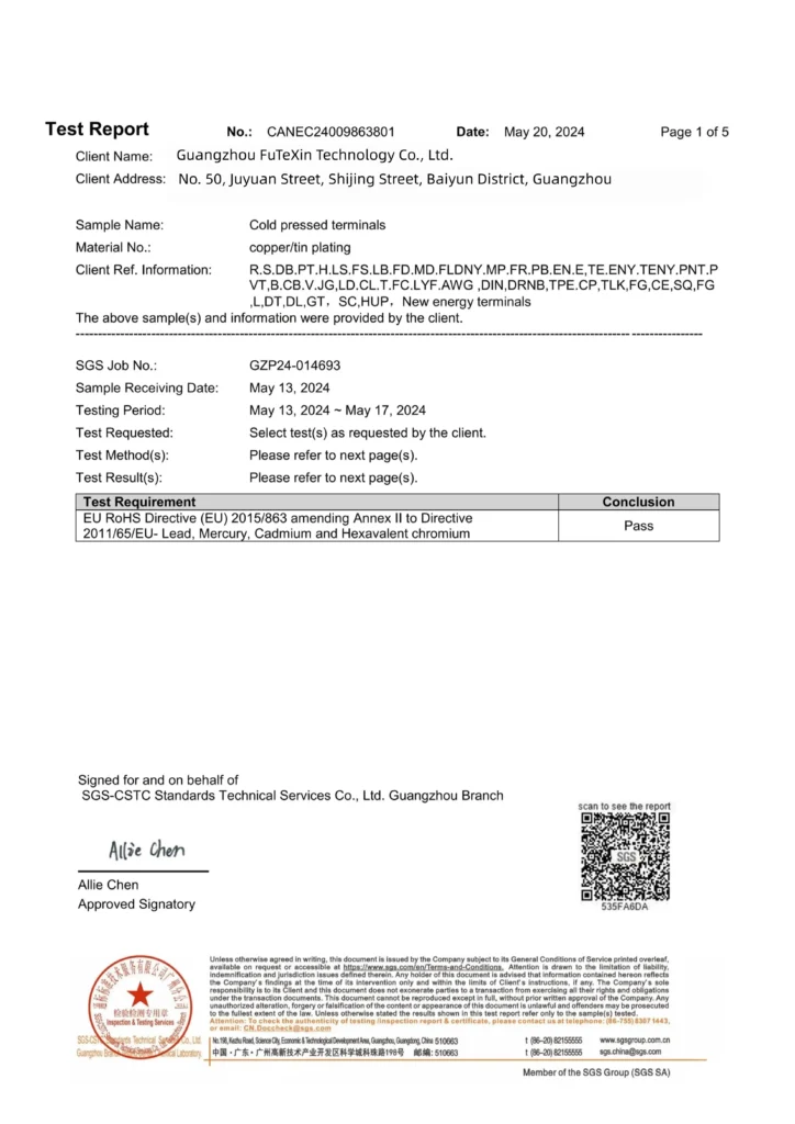
How this guide was written: tab sizes come from the UL 310 and IEC 61210 scope summaries and from Burndy’s QP-F listing. The insulation and barrel notes follow Waytek, TE Connectivity and iCrimp pages, the fit check a Wiltronics article, and the fretting notes two research papers. VoltixC ran no tests for this guide. The six series and their 52 part numbers come from the VoltixC supplier specification sheets and have not each been re-tested.
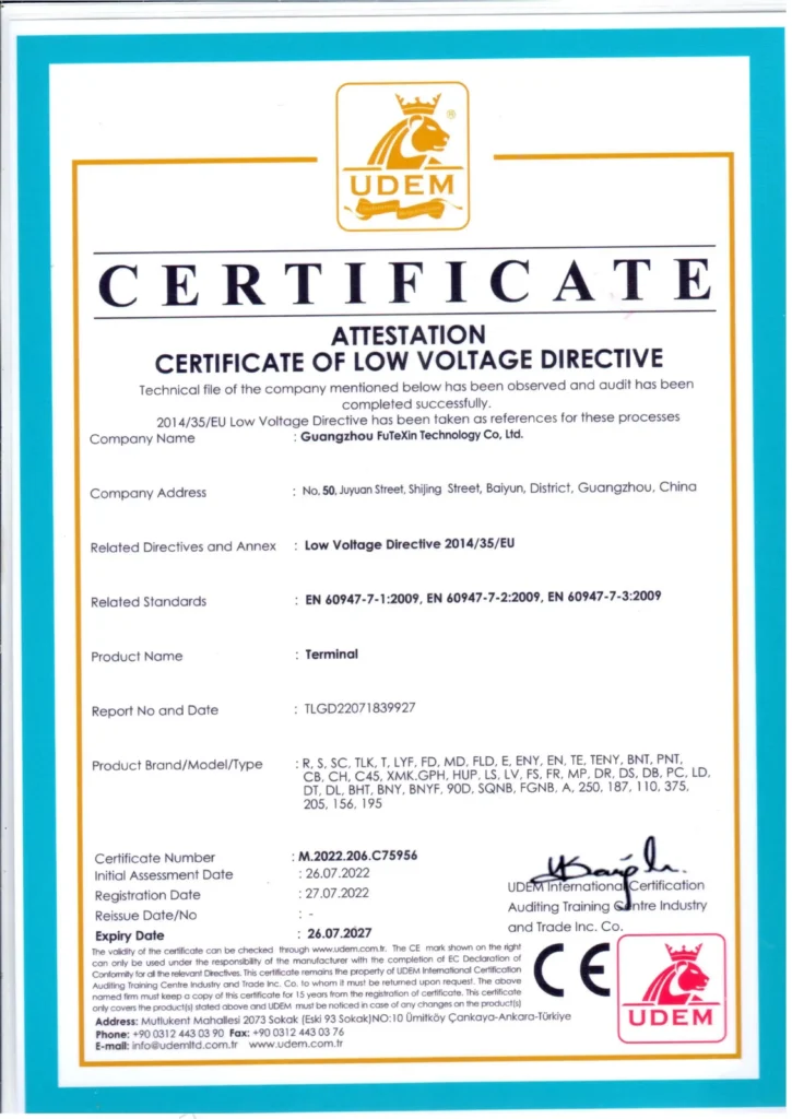
VoltixC is the brand of Guangzhou FuTeXin Technology Co., Ltd. It makes the six quick disconnect series this guide uses as examples; crimp tools are outside its range.