VOLTIXC / ENQUIRY
Request a Quote
Tell us what you need and we will review your enquiry.

By VoltixC Engineering Team · Last updated: 2026-09-28
Fast answer: Grounding connectors come in four main types: mechanical lay-in lugs that accept a continuous conductor, set-screw ground lugs, compression ground lugs, and clamps or clips. Choose by conductor material and size, mounting surface, outdoor exposure and whether the joint must be re-opened. VoltixC lists a lay-in grounding lug for copper conductors (aluminum alloy body, confirmed per order).
Bolt a ground lug to a metal frame, enclosure or rail, clamp the grounding conductor in it, and that metal has a bonded path back to the supply. Lugs hold the conductor with a set screw, a crimped barrel or a weld. Where there is no flat face to bolt to, such as a pipe, a ground rod or a module frame, a clamp or clip takes the lug’s place. VoltixC lists its lay-in type on the grounding lugs page.
Grounding enquiries from solar racking crews, telecom installers and panel builders start at different surfaces: a module rail, a ground bar, an enclosure wall. Pick the connector type for that surface first; the metal, the wire range and the bolt hole follow from it.
Put the connector type and install method at the top of a grounding connector spec, then add wire range, conductor metal, body and plating, hole, listing and environment.
| Spec line | What to record | Where this guide covers it |
|---|---|---|
| Connector type | Lay-in lug, set-screw lug, compression lug, weld-on connection, clip or clamp, or ground bar | Grounding connector types table |
| Install method | Set screw over a laid-in conductor, set screw over a cut end, crimped barrel, or weld; this feature decides whether the conductor has to be cut | Grounding connector types table |
| Wire range and conductor | Conductor size in AWG or mm², copper or aluminum, solid or stranded; the VoltixC lay-in series lists four ranges from 14 AWG to 250 kcmil per supplier specification sheet | Wire size and mounting section |
| Body material and plating | VoltixC lay-in series: terminal body listed as aluminum alloy, tin-plated; confirmed per order | Material and plating section |
| Mounting hole and slot | Bolt or stud size and lay-in slot width; the VoltixC lay-in series takes #10 to 5/16 in bolts per supplier specification sheet, and the slot width is confirmed per order | Wire size and mounting section |
| Equipment the part connects | UL 467 covers equipment that connects power-system grounding conductors and non-current-carrying equipment metal parts, armored grounding wires, or metal raceways to grounding electrodes | Ground lug section |
| Code framework | UL 467 applies to grounding and bonding equipment used under CSA C22.1 in Canada, NFPA 70 in the United States, or NOM-001-SEDE in Mexico | Ground lug section |
| Listing for grounding and bonding | Confirmed per order; naming UL 467 in this guide is not a statement that a VoltixC part carries that listing | Wire size and mounting section |
| Environment | Indoor, outdoor or roof; ASTM B545 states that tin is protective indoors on iron, steel, nickel, copper and their alloys, while outdoor exposure can produce corrosion | Material and plating section |
Source: VoltixC lay-in series per supplier specification sheet; not individually re-tested; other rows from the sources cited below.
Fill in each row before you send the enquiry. Where a row reads confirmed per order, the VoltixC supplier record doesn’t give the field, and your drawing sets the value.
| Also asked as | Short answer | Covered in |
|---|---|---|
| What is a grounding lug; ground lug definition | A lug bolted to equipment metal that clamps the grounding conductor, so a fault on electric equipment has a bonded path back to the supply | What is a ground lug |
| Grounding lug installation | Bolt the lug to a prepared contact face, seat the conductor, then torque the set screw to the value on the lug or in the maker’s instructions | Open slot; mistakes |
| How many ground wires under one lug; can you put two grounds under one lug | One, unless the lug is marked for more; the marking and the maker’s instructions set the count | Mistakes; FAQ |
A ground lug bonds a metal enclosure, frame, raceway or rail to the grounding conductor, so a fault on that metal has an effective path back to the supply.
| Problem | What to do | Check |
|---|---|---|
| A metal enclosure, raceway or cable armor could carry fault voltage | Bond it to the supply through an effective ground-fault current path. In Mike Holt’s NEC excerpt, Article 250.4(A)(3) says metal parts of raceways, cables, enclosures, and equipment must connect to the supply source through an effective ground-fault current path | Every metal part on the run has a bonded joint |
| The design leans on a ground rod to clear a fault | Run an equipment grounding conductor with each circuit; under 250.4(A)(5) in the same excerpt, earth is not suitable as the effective ground-fault current path, so an equipment grounding conductor recognized in 250.118 is required with all circuits | The drawing shows an equipment grounding conductor for each circuit |
| A part joins grounding conductors to equipment metal or to an electrode | Treat it as grounding and bonding equipment. UL 467 covers equipment that connects power-system grounding conductors and non-current-carrying equipment metal parts, armored grounding wires, or metal raceways to grounding electrodes | The part’s documents name a grounding or bonding use |
| The installation falls under a North American electrical code | Read the product standard against the local code; UL Standards & Engagement says UL 467 applies to grounding and bonding equipment used under CSA C22.1 in Canada, NFPA 70 in the United States, or NOM-001-SEDE in Mexico | The code on the drawing is one of the three |
| A general-purpose terminal is offered for a ground connection | Ask for the document that covers its grounding use before accepting it | The quotation names the grounding use or the standard |
| One bare conductor has to bond a row of frames | Fit a lay-in lug at each frame, covered in the open-slot section below | The conductor runs past every frame without a splice |
A ground lug is one joint in that path, so its fit to the conductor and to the bolt face matters as much as the conductor size. Citing UL 467 or the NEC here describes the product class and the code text; it is not a statement that any VoltixC part is listed.
Grounding connectors come in six forms: mechanical lay-in lugs, set-screw ground lugs, compression ground lugs, weld-on connections, grounding clips or clamps, and ground bars. They differ in how the conductor is held, whether the run has to be cut, and whether the joint can be opened again.
| Type | How it holds the wire | Cut the conductor? | Tool needed | Re-enterable | Typical mounting | VoltixC page |
|---|---|---|---|---|---|---|
| Mechanical lay-in lug | Conductor dropped into an open channel and clamped by a set screw | No; the run passes through | Screwdriver or hex key, torqued to the lug maker’s value | Yes, by loosening the screw | Bolted to a rail, frame or enclosure | Lay-In Grounding Lugs |
| Mechanical set-screw ground lug | Cut end pushed into a closed barrel under a set screw | Yes, or the conductor ends at the lug | Screwdriver or hex key, torqued to the lug maker’s value | Yes, by loosening the screw | Enclosure wall, ground stud or bus | aluminum and copper mechanical lugs (general mechanical lugs, shown for comparison) |
| Compression ground lug | Barrel crimped onto the conductor with a matched die | Yes; the conductor ends in the barrel | Crimp tool with the die the lug maker names | No; the crimp is permanent | Bolted to a ground bar or equipment pad | one-hole compression lugs (general compression lugs, not sold as grounding-specific) |
| Weld-on (exothermic) connection | Conductor fused to steel or to another conductor | Depends on the joint | Mold and weld material | No | Structural steel, ground rods, conductor splices | Shown for comparison only |
| Grounding clip or clamp | Saddle or screw clamps the conductor to a pipe, rod or frame | No | Wrench or screwdriver | Yes | Pipes, ground rods, racking and module frames | Shown for comparison only |
| Ground bar | Several conductors land under screws on one bar | Conductors end at the bar | Screwdriver | Yes | Inside panels and telecom cabinets | Shown for comparison only |
Pick a lay-in lug when one bare conductor bonds a row of frames and should stay whole. A compression lug suits a conductor that ends at the equipment, where the joint should stay closed for good. The set-screw lug sits between them: the conductor ends there, yet the screw can be opened for inspection.
| Where the type meets the code | What the source says | Source |
|---|---|---|
| Splicing a grounding electrode conductor | NEC 250.64(C)(1), as reproduced by ICC, permits splicing a wire-type grounding electrode conductor only by irreversible compression-type connectors listed as grounding and bonding equipment, or by exothermic welding | ICC Digital Codes, NEC 250.64 |
| Tapping a grounding electrode conductor | Under 250.64(D)(1) in the same ICC text, taps connect by exothermic welding, connectors listed as grounding and bonding equipment, or a busbar connection | ICC Digital Codes, NEC 250.64 |
| Clamps, bushings and bonding devices | UL 467 covers grounding-system equipment such as ground clamps, bonding devices, grounding bushings, water-meter shunts, and grounding electrodes | UL Standards & Engagement, UL 467 |
| Bonding other systems at the service | UL 467 includes intersystem bonding terminations for connecting intersystem bonding and grounding conductors for other systems in accordance with NFPA 70 | UL Standards & Engagement, UL 467 |
| One maker’s listing example | ILSCO’s Form 2 gives UL 486A-B and UL 467 listings, with certification for Canada, to its CP-8, CP-4, CP-0 and CP-250; its CP-500 and CP-1000 carry UL 486A-B only and are not for compact copper wire | ILSCO Form 2 |
Source: code and standard rows as cited in each row; the ILSCO row is one maker’s example.
Listing check: When a clause in 250.64 asks for a connector listed as grounding and bonding equipment, the listing belongs to the part in your hand. Ask the supplier which listing the part carries; this guide quotes the clause and does not state that any VoltixC part meets it.
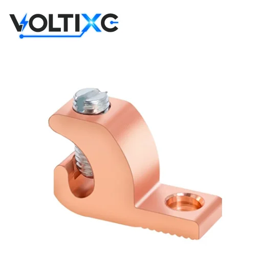
The open slot lets you drop a continuous grounding conductor into the lug partway along its run and clamp it with the set screw, so one conductor bonds several frames without a cut.
| Problem | What to do | Check |
|---|---|---|
| One bare conductor has to bond a row of module rails or cabinets | Bolt a lay-in lug to each rail, then lay the conductor into each slot in turn | The conductor passes every lug in one uncut length |
| A closed-barrel lug would force a cut and a splice between two frames | Swap that joint for a lay-in lug and keep the run whole | No splice sits between two frames |
| The slot looks roomy for the conductor | Match the conductor to the size range marked on the lug or its data sheet; the VoltixC lay-in series prints four ranges from 14 AWG to 250 kcmil | The conductor size sits inside the marked range |
| The set screw is about to be tightened | Torque it to the value marked on the lug or given in the lug maker’s instructions; for the VoltixC series that value is confirmed per order | A torque tool reached the stated value |
| Two conductors could fit the slot | Put a second conductor in only when the lug marking or instructions allow two | The marking names the conductor count |
| The lug sits on painted or coated metal | Prepare the contact face the way the equipment maker’s instructions say | The lug body seats on the prepared face |
The slot saves the cut and changes nothing else about the joint. Where the conductor ends at the lug, a set-screw or compression lug from the types table fits the job better.
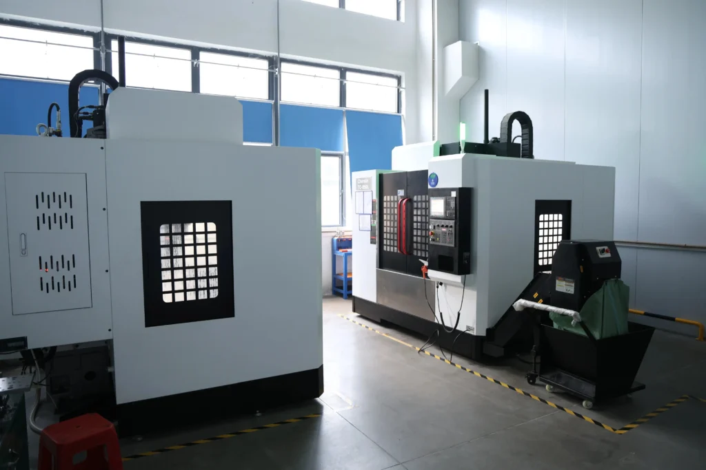
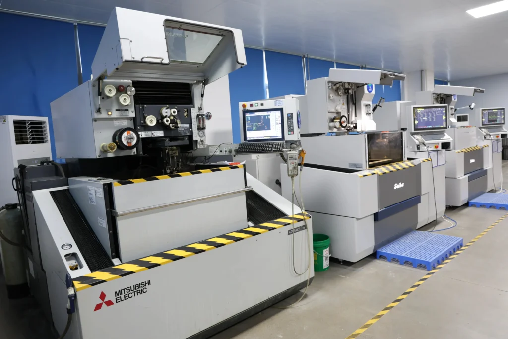
Match the connector to the conductor metal first, with a copper or tinned copper lug for copper and a lug marked for aluminum when the conductor is aluminum, then check how that lug metal sits against the frame outdoors.
| Question | What the source says | What to do |
|---|---|---|
| What drives corrosion at a joint | NASA Kennedy Space Center defines galvanic corrosion as an electrochemical action involving two dissimilar metals, an electrolyte, and an electron-conductive path | Keep water off the contact faces where copper meets aluminum or steel |
| How much the metal mismatch matters | Per the same NASA KSC page, the farther apart metals are in the galvanic series, the greater the galvanic-corrosion effect or rate | Pick a lug metal close to the frame metal |
| How corrosion can be controlled | NASA KSC lists two controls: selecting metals closer in the galvanic series or electrically isolating them | Use the first control on a bonding joint; the joint has to conduct, so isolating it defeats the purpose |
| What tin plating does | ASTM B545 states that tin is protective indoors on iron, steel, nickel, copper, and their alloys, while outdoor exposure can produce corrosion | Count tin as one layer of protection outdoors and still check the pairing |
Source: NASA Kennedy Space Center corrosion pages and ASTM B545, as cited in each row.
Aluminum conductors need a lug marked for aluminum, and the strands need the preparation the lug maker gives; the mistakes table below quotes ILSCO’s brushing and inhibitor step. On roofs and coastal sites, send the frame metal with the conductor metal so both sides of the joint are known. The VoltixC lay-in series is sold for a bare copper conductor. Its terminal body is listed as aluminum alloy, tin-plated; confirmed per order.
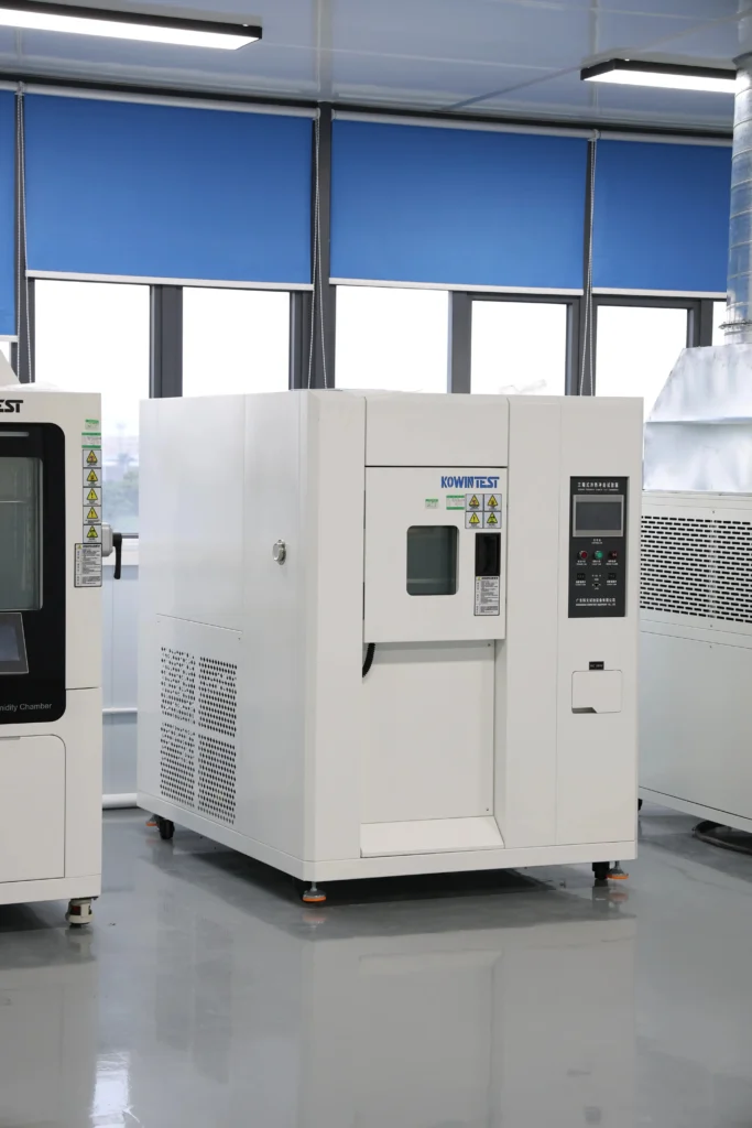
Read the wire range first, then the conductor metal the lug is marked for, then the mounting hole and screw drive, and finish by checking the body metal against the surface it bolts to.
| Spec column | What it tells you | VoltixC lay-in series |
|---|---|---|
| Wire range (AWG / mm²) | The conductor sizes the slot or barrel accepts | 14–4 AWG, 8–1/0 AWG, 6–3/0 AWG and 6 AWG–250 kcmil |
| Conductor material | Copper, aluminum, or both | Bare copper conductor, as listed for the series |
| Body material and plating | The lug’s own metal and coating | Terminal body listed as aluminum alloy, tin-plated; confirmed per order |
| Mounting hole | Bolt or stud size for the lug body | #10, 1/4 in or 5/16 in bolt, by wire range |
| Screw drive | The drive the set screw takes | Not stated; confirmed per order |
| Lay-in slot width | The largest conductor the open channel takes | Confirmed per order |
| Listing | The standard the part is listed to, shown by a mark on the part or its label | Ask which document applies to the item you order |
Source: VoltixC lay-in series per supplier specification sheet; not individually re-tested; blank fields confirmed per order.
Grounding lug size follows the conductor on the drawing, and the bolt sets the hole. If the drawing gives mm² and the lug data gives AWG, the cable lug size chart converts one to the other.
Worked example: A drawing shows a bare 6 AWG copper conductor bonding aluminum racking rails, one bolt per rail. The lug’s marked range has to include 6 AWG, the lug has to be marked for copper, its hole has to take the rail bolt, and its body metal has to be checked against the aluminum rail. Those four lines go into the enquiry.
The listing row is where buyers slip. According to UL Solutions, grounding and bonding equipment is evaluated to UL 467, with support for Canada and Mexico where applicable. UL Solutions also notes that listings meeting applicable U.S./Canada requirements can enable a UL/C-UL Listing Mark. A data sheet that names UL 467 with no mark on the part names the standard and nothing more.
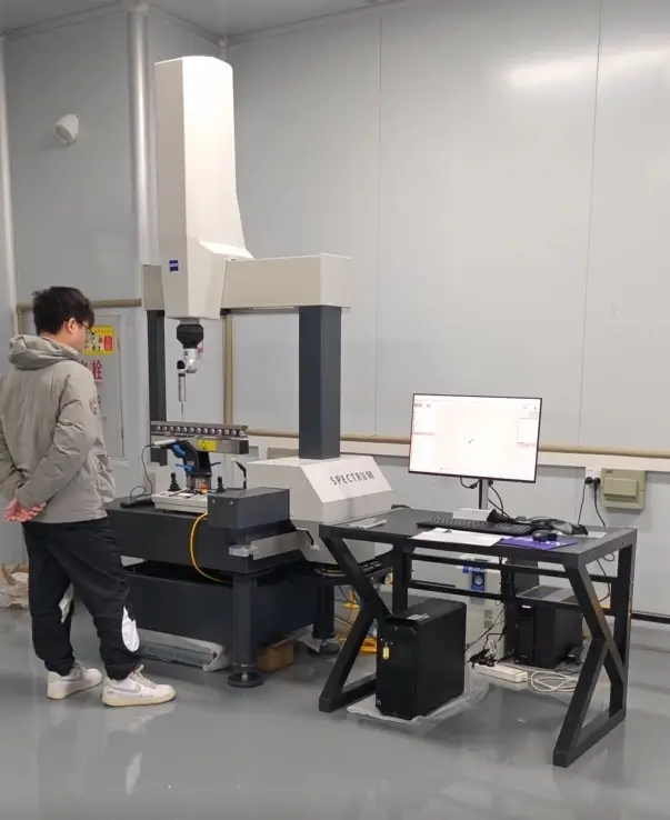
On solar racking, use a lay-in lug or a clip the racking maker names; at a telecom cabinet, land compression lugs on the ground bar; inside a panel, use the enclosure’s ground bar or a mechanical lug for larger conductors.
| Scenario | Mounting surface | Environment | Recommended type | Series |
|---|---|---|---|---|
| Solar module rows on racking | Aluminum rail or module frame | Outdoor, roof or ground mount | Lay-in lug on a bare conductor run, or the clip the racking maker names | lay-in grounding lugs |
| Combiner box or inverter enclosure on a roof | Enclosure wall or ground stud | Outdoor, roof | Set-screw or compression lug at the enclosure’s grounding point | mechanical lugs |
| Telecom cabinet or shelter | Ground bar inside the cabinet | Indoor or sheltered | Compression lug on each conductor, bolted to the bar | compression lugs |
| Tower, mast or structural steel bond | Steel member or ground rod | Outdoor | Clamp or weld-on connection as the site standard sets out | Shown for comparison only |
| Distribution panel, home or commercial | Ground bar in the enclosure | Indoor | Screw terminal on the bar, or a mechanical lug for a larger conductor | copper mechanical lugs |
| Equipment rack or cable tray bond | Painted steel rack or tray | Indoor | Lay-in or set-screw lug on a prepared contact face | lay-in ground lugs |
The racking, cabinet or panel maker’s instructions name the connector and the fastening point for their own equipment, and those instructions outrank this table. Send the row that matches your job along with the conductor size, and the lug is quoted against it.
Ground paths open at the joint: oxide left on aluminum strands, a lug not marked for the conductor metal, the wrong crimp die, a set screw short of its torque, and an unsuited metal pairing outdoors.
| Problem | What to do | Check |
|---|---|---|
| Oxide film left on an aluminum conductor | Brush and treat the strands: according to the ILSCO installation guide, aluminum conductors should be brushed with a stainless steel wire brush to remove oxide film and treated with oxide inhibitor compound | Strands bright and inhibitor on before the lug closes |
| Copper-only lug on an aluminum conductor | Swap it for a lug marked for aluminum, or one marked for both metals | The lug marking names aluminum |
| Fine-strand or flexible conductor in a lug made for standard stranding | Ask whether the lug suits that strand class before it goes on | The data sheet names the strand class |
| Compression lug crimped with a die from another maker’s chart | Use the die the lug maker names, since die color codes vary by maker; the wire crimping guide covers die matching | Die marking and lug barrel marking agree |
| Set screw tightened by feel | Torque it to the value on the lug or in the maker’s instructions; the torque guide for mechanical lugs explains where the values come from | A torque tool reached the stated value |
| Two ground wires under a lug marked for one | Fit a second lug, or a lug marked for two conductors | Conductor count matches the marking |
| Dissimilar metals paired outdoors | Choose metals closer in the galvanic series; NASA KSC states that the farther apart metals are in the galvanic series, the greater the galvanic-corrosion effect or rate | Lug-to-frame pairing checked for outdoor exposure |
| Tin plating treated as outdoor-proof | Plan outdoor inspection anyway: in ASTM B545, tin is protective indoors on iron, steel, nickel, copper, and their alloys, while outdoor exposure can produce corrosion | Outdoor joints are on the inspection list |
A bad joint stays hidden until a fault needs the path. Buyers ask whether two grounds can share one lug; the marking on the lug answers that, and the FAQ below repeats the rule.
Earth path: Keep the equipment grounding conductor even where a ground rod is driven. Under 250.4(A)(5), as excerpted by Mike Holt, earth is not suitable as the effective ground-fault current path, so an equipment grounding conductor recognized in 250.118 is required with all circuits.
Start on the VoltixC grounding lugs page, which lists one lay-in series for a bare copper conductor (terminal body listed as aluminum alloy, tin-plated; confirmed per order), and send your conductor size, conductor metal and mounting surface with the enquiry.
When the conductor ends at the lug, the mechanical lugs hub and the one-hole compression lug page carry the closed-barrel options. The trade-off between the two is set out in compression vs mechanical lugs, and the guide to choosing cable lugs covers the other lug shapes.
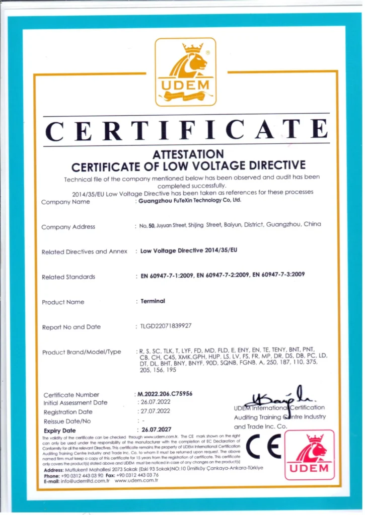
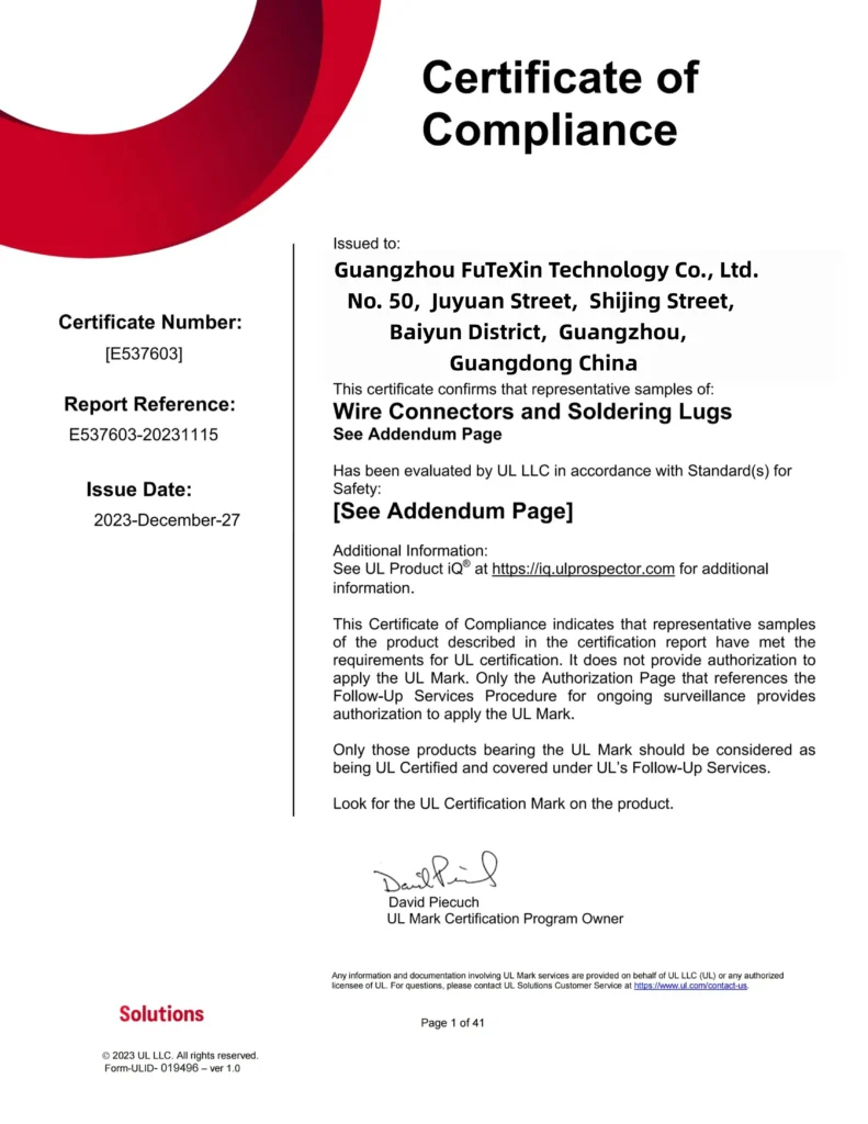
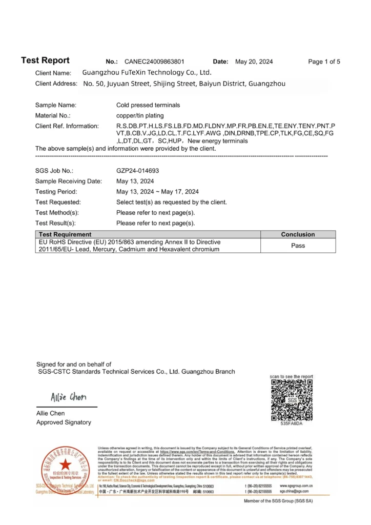
The three images are on file at VoltixC: CE under the Low Voltage Directive 2014/35/EU for the full terminal range, UL certified, and RoHS test report available (SGS). Their numbers and dates are not published here, and none of them is presented as a UL 467 listing for the lay-in lug.
It’s the bolted joint between the equipment metal and the grounding conductor. If a fault puts voltage on an enclosure, the current leaves through that lug and returns to the supply along the conductor. A loose or corroded lug adds resistance at a spot nobody looks at, so check its torque and contact face when you install it.
In an open slot under a set screw. Lay the bare conductor in at any point along the run, tighten the screw, and carry the same conductor on to the next lug. Torque comes from the lug marking or the maker’s sheet.
Tinned copper suits a copper lug that will sit in damp air. It does not make the joint weatherproof: ASTM B545 states that tin is protective indoors on iron, steel, nickel, copper, and their alloys, while outdoor exposure can produce corrosion. On a roof or near the sea, check what the lug touches as well, because the metal pairing matters as much as the plating.
Three sizes: the conductor in AWG or mm², the bolt or stud for the mounting hole, and the slot width if your conductor is near the top of a range. Name the set-screw drive only if your crew needs a particular bit, and say what the conductor and the mounting surface are made of. Our lay-in series has two of these in its supplier record, so the third is confirmed per order.
A lay-in lug or the racking maker’s clip on solar rails; compression lugs on the ground bar in a telecom cabinet; the enclosure’s ground bar, or a mechanical lug for a big conductor, in a panel. When the equipment maker names a connector, use that one.
Oxide on aluminum strands, a lug not marked for the conductor metal, a crimp die from the wrong chart, a set screw short of its torque, and two wires under a one-wire lug. For the first, ILSCO’s installation guide says aluminum conductors should be brushed with a stainless steel wire brush to remove oxide film and treated with oxide inhibitor compound. You catch the other four by reading the lug marking before anything is tightened.
One, unless the lug is marked for more. Two conductors might fit in the slot, and the marking still decides the count, along with the maker’s instructions. We quote the VoltixC lay-in lug for one conductor unless the agreed drawing says otherwise.
How this guide was written: it draws on the UL 467 page from UL Standards & Engagement, the UL Solutions grounding evaluation page and Mike Holt’s NEC 250.4 excerpt. The NEC 250.64 text reproduced by ICC, ILSCO’s Form 2 and installation guide, NASA Kennedy Space Center’s corrosion pages and ASTM B545 supply the rest. VoltixC ran no tests for this guide, so it gives no torque, resistance or corrosion values. The lay-in series data comes from VoltixC supplier records as listed and has not been re-tested.
VoltixC is the brand of Guangzhou FuTeXin Technology Co., Ltd. It lists the lay-in grounding lug, mechanical lugs and compression lugs that this guide links to.