VOLTIXC / ENQUIRY
Request a Quote
Tell us what you need and we will review your enquiry.

By VoltixC Engineering Team · Last updated: 2026-09-28
Fast answer: Mechanical lug torque specs come first from the lug marking or the equipment installation instructions, then from the manufacturer’s published chart for that exact part. Match the value to conductor size and screw drive, apply it with a calibrated torque tool and log the setting; VoltixC confirms values per part number on request rather than publishing a generic chart.
A mechanical lug clamps the conductor under one or more set screws instead of a crimped barrel. The screw torque presses the strands against the lug body, so a value taken from the wrong chart leaves the screw loose or over-driven. Neither fault shows on the day of installation; it turns up later as heat at the joint or as broken strands.
VoltixC lists 100 mechanical lug part numbers in two series, AM with an aluminum body and CM with a body listed as aluminum alloy, on its copper mechanical lugs page. That specification table has no torque column. Every torque figure below is a third-party example with its source in the same row, and the value for a VoltixC part is confirmed against its part number when you ask.
Record the torque value from the lug marking or the installation instructions, together with the lug part, the conductor, the tool ID and the tool’s calibration date.
| Check | Field to confirm | Working value |
|---|---|---|
| Torque source | Lug marking, then the equipment installation instructions, then the maker’s chart for that part number | Write down which document gave the value |
| Lug family | AM (aluminum body) or CM (body listed as aluminum alloy) series | VoltixC lists 48 AM and 52 CM part numbers per supplier specification sheet |
| Conductor fit | AWG–kcmil or mm² range printed for the lug | Confirmed per order for VoltixC parts, whose sheets print a range per part number from #14 AWG on AM0614 to 1000 kcmil on AM1151; UL Standards & Engagement lists copper conductor ranges of 30 AWG through 10 AWG solid and 30 AWG through 2,000 kcmil stranded for UL 486A-486B |
| Conductor material | Copper or aluminum, and whether the lug is marked for aluminum | Aluminum ranges for UL 486A-486B are 12 and 10 AWG solid, 12 AWG through 2,000 kcmil stranded, and 12 AWG through 1,000 kcmil stranded single-input wire (UL Standards & Engagement) |
| Conductor stranding | Standard or compact-stranded copper | Per UL Standards & Engagement, compact-stranded copper conductors are covered from 8 AWG and larger in Canada and Mexico, and from 2 AWG and larger in the United States |
| Screw drive | Slotted, external hex or internal socket | The drive changes the value; ILSCO Form 1 gives 35 in-lb with a screwdriver for 14 AWG, 12 AWG, and 10 AWG mechanical screw connectors |
| Torque value | The in-lb figure from the document in the first row | VoltixC values are confirmed per part number on enquiry |
| Tool ID and calibration date | Serial or asset number of the torque tool and its last calibration date | Both go on the same log line as the torque value |
Source: VoltixC rows per supplier specification sheet, not re-tested; other rows from the sources cited below.
Keep one log line per termination. When the lug marking and a chart disagree, the marking decides and the chart value stays off the log.
| Also asked as | Short answer | Covered in |
|---|---|---|
| Torque values for mechanical lugs | Taken from the lug marking or the equipment instructions first, then from the maker’s chart for that part number | Where the torque value comes from |
| Electrical lug torque specs | The same source order applies to any set-screw lug, whether it lands on a bus, a stud or a breaker terminal | Where the torque value comes from |
| NEC electrical lug torque specs chart | A search for a code chart; for a listed lug, log the value marked on the lug or given in the maker’s instructions | Where the torque value comes from; FAQ |
| Torque chart for electrical lugs | Torque varies with conductor size and screw drive, so the chart gives each drive its own column and each size band its own row | How the torque chart is organised |
A mechanical lug is a terminal that clamps the conductor with a set screw, and the torque on that screw sets the clamping force: too little lets the joint loosen and heat up, too much crushes strands or damages the screw thread.
| Problem | What to do | Check |
|---|---|---|
| The set screw is under-torqued and the conductor can shift in the barrel as the connection goes through thermal cycles | Re-make the termination at the value from the lug marking, with a calibrated torque tool | The conductor stays put when pulled, and the log shows the setting |
| The screw was driven past the marked value | Cut back to undamaged conductor and terminate again; replace the lug if the screw or its thread is damaged | Strands under the screw are round and whole, and the screw turns freely in its thread |
| The conductor size sits outside the lug’s printed range | Pick a lug whose range covers the conductor instead of adding torque to close the gap | The conductor size falls between the minimum and maximum marked on the lug |
| Conductor ampacity is being picked from the insulation rating alone | Read the temperature rating marked on the lug and on every connected device. According to Electrical Contractor Magazine, NEC 110.14(C) requires conductor ampacity temperature selection to stay at or below the lowest temperature rating of any connected termination, conductor, or device | The temperature column used for ampacity is no higher than the lowest rating in the circuit |
| Several conductors have to land on one lug | Use a lug body made for that number of conductors; the VoltixC AM list includes 2-conductor and 4-conductor bodies such as AM3106-21S and AM2506-44 | Each port has its own conductor and its own log line |
| You are still choosing between a set-screw lug and a crimped lug | Compare the two routes in the compression and set-screw lug comparison | The route matches the tools and inspection method on site |
Torque and temperature rating are two separate markings, and one lug can carry both. Read each from the lug body or its instruction sheet before the first screw turns; a missing value goes back to the lug maker as a question before installation.
Read the torque off the lug first. Without a marking, take it from the equipment’s installation instructions, then from the maker’s chart for that exact part number; a generic default chart comes last and needs the lug maker’s confirmation. For VoltixC AM and CM lugs, send the part number and the value comes back confirmed per part number.
| Problem | What to do | Check |
|---|---|---|
| The lug body or its label carries a torque value | Use that value as printed | The log line quotes the marking word for word |
| The lug sits in equipment with its own installation instructions | Follow those instructions. Mike Holt’s NEC changes article notes that listed, labeled, or identified equipment must be installed in accordance with the manufacturer’s instructions under Section 110.3(B) | The instruction sheet is named on the log |
| Neither a marking nor equipment instructions exist | Find the lug maker’s published chart for that exact part number | The chart row names your part and your conductor range |
| Only a generic default chart is at hand | Treat its figure as a placeholder and ask the lug maker’s technical support before sign-off | A written reply from the maker replaces the default figure |
| The lug is a VoltixC AM or CM part | Send the part number with the conductor size and material; the value is confirmed per part number on enquiry | The confirmed value is on file before installation starts |
| A drawing names UL 486A-486B | Read it as the connector standard. On the UL Standards & Engagement page, UL 486A-486B applies to single-polarity connectors used with copper, aluminum, or copper-clad aluminum conductors in installations governed by the Canadian Electrical Code, NFPA 70, or NOM-001-SEDE | The standard is quoted for scope only |
| A supplier mentions UL testing of its connectors | Ask which service and which standard were used; UL Solutions names UL 486A-486B (Wire Connectors) as one of the U.S. standards it uses to evaluate wire connectors for compliance and safety | The answer names a standard and a product category |
| The part might be an equipment-wiring terminal rather than a separate lug | Check the product category. UL Solutions says its wire-connector certification services cover terminal connectors, splicing wire connectors, insulating caps or covers, soldering lugs, wire-connector adapters, sealed systems, uninsulated equipment-wiring terminals, ferrules, and sealed twist-on-style splicing connectors | The category on the paperwork matches the part in your hand |
This guide does not assign a torque number when the matching product record or label is unavailable. If two documents disagree about one screw, go with the one higher up the table.
A mechanical lug torque chart lists conductor sizes in rows and gives each screw drive its own torque column, so find the drive first and the size second.
Slotted screws, external hex heads and internal sockets get separate columns because one conductor can take a different value with each drive. Sizes climb from AWG into kcmil down the same column, and the heaviest conductors sit at the bottom of the sheet. The ILSCO Form 1 sheet quoted below works in in-lb, and ILSCO Form 18 puts ft-lb in brackets beside it. Whichever unit the sheet uses, set your tool in that unit.
| Column | What it holds | VoltixC AM / CM entry |
|---|---|---|
| Series | The product family the chart covers | AM (aluminum body) or CM (body listed as aluminum alloy) |
| Part | The part number that the value belongs to | Part number from the VoltixC list, such as AM0614 or CM1414A |
| Wire range | Minimum and maximum conductor, in AWG–kcmil or mm² | Printed per part number, such as #14 AWG–#6 AWG on AM0614 |
| Screw drive | Slotted, external hex or internal socket | Slot or hex size printed per part number |
| Recommended torque | One value for each drive and size band, with its unit | Confirmed per part number on enquiry |
| Conductor | Copper, aluminum or both, as marked on the lug | Body listed as aluminum for AM and aluminum alloy for CM; conductor marking confirmed per order |
| Drive and size band | What the chart says | Source |
|---|---|---|
| Screwdriver, 14 to 10 AWG | 14 AWG, 12 AWG, and 10 AWG mechanical screw connectors use 35 in-lb with a screwdriver | ILSCO Form 1 |
| Screwdriver, 8 AWG to 2/0 AWG | Screwdriver tightening torque is 40 in-lb for 8 AWG, 45 in-lb for 6/4 AWG, and 50 in-lb for 2 through 2/0 AWG | ILSCO Form 1 |
| External drive wrench, 14 AWG to 2/1 AWG | External-drive-wrench torque is 75 in-lb for 14 through 8 AWG, 110 in-lb for 6/4 AWG, and 150 in-lb for 2/1 AWG | ILSCO Form 1 |
| External drive wrench, 1/0 to 4/0 AWG | External-drive-wrench torque is 180 in-lb for 1/0 and 2/0 AWG and 250 in-lb for 3/0 and 4/0 AWG | ILSCO Form 1 |
| External drive wrench, 250 and 350 kcmil | External-drive-wrench torque is 325 in-lb for 250 and 350 kcmil conductors | ILSCO Form 1 |
| External drive wrench, 500 to 1000 kcmil | External-drive-wrench torque is 375 in-lb for 500 through 750 kcmil and 500 in-lb for 800 and 1000 kcmil | ILSCO Form 1 |
| Internal socket (hex key) | Sockethead screw connector torque ranges from 45 to 600 in-lb for internal socket sizes across flats from 1/8 to 9/16 inch | ILSCO Form 1 |
| Connector and wiring | What the chart says | Source |
|---|---|---|
| CP-8, one conductor | CP-8 connectors for a single 8 AWG solid/stranded copper wire use 25 in-lb; 10–14 AWG solid/stranded use 10 in-lb | ILSCO Form 2 |
| CP-4, one conductor | CP-4 single-wire torque is 45 in-lb for 4–6 AWG stranded or 6 AWG solid, 40 in-lb for 8 AWG, and 35 in-lb for 10–18 AWG | ILSCO Form 2 |
| CP-4, wire combinations | CP-4 wire combinations use 40 in-lb for two 8 AWG conductors and 35 in-lb for two 10/12/14 AWG or four 16 AWG conductors | ILSCO Form 2 |
| CP-0, one conductor | CP-0 single-wire torque is 200 in-lb for 1/0–6 AWG stranded or 2–6 AWG solid, and 50 in-lb for 8–10 AWG | ILSCO Form 2 |
| CP-0, wire combinations | CP-0 wire combinations use 200 in-lb for two 6 AWG conductors and 50 in-lb for two 8 AWG conductors | ILSCO Form 2 |
| CP-250, one conductor | CP-250 single-wire connectors use 200 in-lb for 250 kcmil–6 AWG stranded or 2–6 AWG solid copper wire | ILSCO Form 2 |
| CP-500 and CP-1000 | CP-500 uses 375 in-lb for 500 kcmil–2/0 AWG stranded copper wire, while CP-1000 uses 500 in-lb for 1000–500 kcmil stranded copper wire | ILSCO Form 2 |
Source: ILSCO Form 1 and ILSCO Form 2 as named in each row; values for those ILSCO parts only, shown as examples and not as VoltixC values.
Combination rows apply when two or four conductors share one barrel. According to ILSCO Form 2, CP-4 wire combinations use 40 in-lb for two 8 AWG conductors and 35 in-lb for two 10/12/14 AWG or four 16 AWG conductors. Pick the row for the number of wires actually in the barrel.
Standards set the outer size span that charts work within. UL 486E, the standard for equipment wiring terminals, covers copper conductors from 30 AWG to 10 AWG solid and 30 AWG to 2,000 kcmil stranded in specified Class B or Class C constructions. It applies to terminals on equipment and is not a standard for a separate mechanical lug body.
Spec note: Read the drive column before the size row. On ILSCO Form 1, an 8 AWG conductor takes 40 in-lb with a screwdriver, and 75 in-lb is the external-drive-wrench value for 14 through 8 AWG.
Pick the lug by its wire range first, the smallest and largest conductor the barrel takes, and then check body length, width, height, mounting hole and screw size against the space in the enclosure.
A range-taking lug accepts every conductor between those two printed sizes, which lets one part serve several sizes on a job. Standards draw much wider bands: UL Standards & Engagement lists copper conductor ranges of 30 AWG through 10 AWG solid and 30 AWG through 2,000 kcmil stranded for UL 486A-486B. Compact-stranded copper has its own starting point there, from 2 AWG and larger in the United States and from 8 AWG and larger in Canada and Mexico (UL Standards & Engagement). Check your conductor against the lug’s own printed range, and let the standard band stay in the background.
| Dimension | What to check | VoltixC AM / CM listing |
|---|---|---|
| Wire range (min to max) | The conductor sits between the two printed sizes | Printed per part number, from #14 AWG (AM0614, CM1414A) to 1000 kcmil (AM1151) |
| Overall length | Clearance to the next terminal or to the enclosure wall | Lettered dimensions (A, B, C, H) per part number on the supplier drawing; ask for the drawing with your quote |
| Width | Spacing between neighbouring lugs on a bus bar | On the same lettered drawing |
| Height | Room for the torque tool above the set screw | On the same lettered drawing |
| Mounting hole | Hole size and hole count against the bolt and nut or the stud | Bolt size printed per part number, such as 1/4 in on AM0614 and 5/8 in on AM1151 |
| Screw size and drive | Bit or hex key size for the set screw | Slot or hex size printed per part number, such as 9/16 in on AM1151 |
| Conductor ports | One barrel per conductor | Multi-conductor AM bodies are listed, such as the four-conductor AM2506-44 in the AM and CM part tables |
| Weight | Load on a bus bar or stud | Confirmed per order |
Convert AWG and mm² for crimped lugs with the cable lug size chart. For bonding and ground terminations, the lay-in parts are on the grounding lugs page.
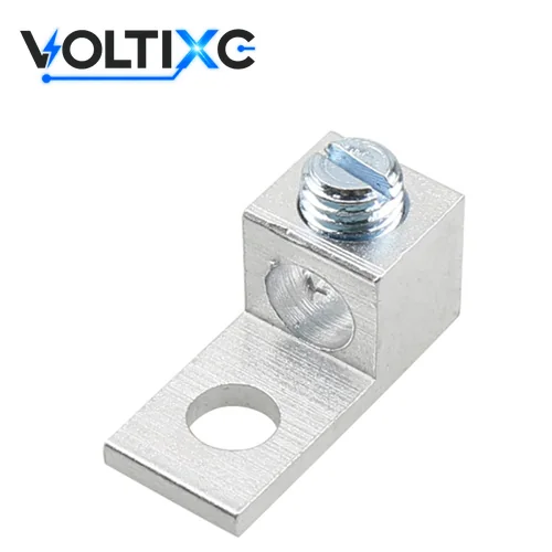
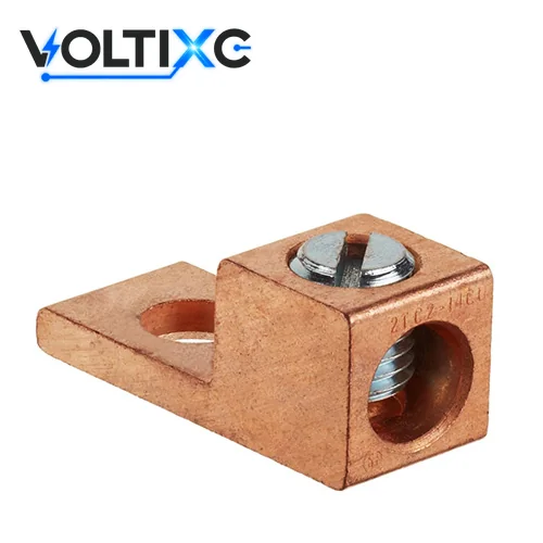
Aluminum conductors need a lug marked for aluminum, the torque value from that lug’s own marking or sheet, and any compound instruction its maker states; VoltixC makes no AL9CU marking claim for its lugs.
| Problem | What to do | Check |
|---|---|---|
| An aluminum conductor is headed for a lug marked for copper only | Choose a lug marked for aluminum. According to UL Standards & Engagement, the aluminum conductor ranges listed for UL 486A-486B are 12 and 10 AWG solid, 12 AWG through 2,000 kcmil stranded, and 12 AWG through 1,000 kcmil stranded single-input wire | The marking on the lug names aluminum |
| A dual-rated socket screw connector takes #14 to #3 AWG | Set the tool from that connector’s own sheet; ILSCO Form 18 gives 120 in-lb (10 ft-lb) torque for UTILCO dual-rated socket screw connectors for #14 AWG to #3 AWG | The tool is set in the unit the sheet uses |
| The same connector line takes #2 AWG to 350 kcmil | Move to the next row of the sheet: 240 in-lb (20 ft-lb) torque for UTILCO dual-rated socket screw connectors for #2 AWG to 350 kcmil, per ILSCO Form 18 | The row chosen matches the conductor size, not the lug size |
| The conductor is 400 to 750 kcmil | Use the larger setting. In ILSCO Form 18, UTILCO dual-rated socket screw connectors for 400 to 750 kcmil use 360 in-lb (30 ft-lb) torque | The torque tool’s range reaches the setting |
| The conductor is 800 to 1000 kcmil | Check the tool range before you start; ILSCO Form 18 lists 480 in-lb (40 ft-lb) torque for UTILCO dual-rated socket screw connectors for 800 to 1000 kcmil | Tool ID and range are on the log |
| The lug sheet states an anti-oxidant compound for aluminum | Apply the stated compound to the prepared conductor before it goes into the barrel | The compound named on the log matches the sheet |
| A drawing calls for AL9CU lugs | Ask the lug maker which marking that exact part carries | The AL9CU marking is on the part itself; VoltixC does not state one |
The UTILCO values are one maker’s example for one product line. The brushing and inhibitor step for aluminum conductors is in the inspection table in the mistakes section below.
Use a calibrated torque tool at the marked value, hold it at the setting, follow the maker’s re-torque instruction, then log and mark each termination.
Set a calibrated torque wrench or torque screwdriver to the value from the lug marking or the installation instructions.
The calibration label on the tool has to be in date before the first joint.
Seat the conductor fully in the barrel and tighten the set screw in one steady pull until the tool signals, then hold at the setting.
When you tug the conductor afterwards, it stays where it is.
Read the lug maker’s instructions for a re-torque step before you move on to the next lug.
If a re-torque is called for, its timing goes on the log next to the first setting.
Write the torque value, its source document, the tool ID and the calibration date into the torque log for that termination.
Each line names the lug part and the conductor it holds.
Mark or tag the finished termination the way your site procedure asks.
An inspector should be able to match every mark to one line in the log.
Some connector sheets add their own fitting steps. On ILSCO’s transformer stud-mounted connectors, Form 18 says the connector should be fully slipped onto the stud and its mounting set screws tightened to 180–220 in-lb; that figure belongs to that product only. Aluminum bolted joints have a hardware point as well: Electrical Engineering Portal notes that spring-pressure hardware such as cupped or split washers is needed to prevent loosening in aluminum bolted joints.
| Log field | What to write |
|---|---|
| Date | The day the termination was torqued |
| Technician | Name or ID of the person who applied the torque |
| Lug part | Part number from the lug or its packaging |
| Conductor size and material | The AWG or kcmil size, and copper or aluminum |
| Torque value | The figure used, its unit and the document it came from |
| Tool ID | Serial or asset number of the torque tool |
| Calibration date | Last calibration date on the tool’s label |
| Re-torque done | Yes, no, or not required by the instructions |
Tip: Set the tool in the unit the source document uses. If the sheet gives in-lb and your tool reads N·m, convert once, write both figures on the log line and have a second person check the conversion.
Tightening with a standard ratchet fails an inspection on its own. So does releasing the tool at the click, taking a generic chart value when the lug is marked, or using a torque wrench whose calibration date has passed. On the conductor side, inspectors reject aluminum in a copper-only lug and small conductors torqued to a large-conductor value.
| Problem | What to do | Check |
|---|---|---|
| A standard ratchet or driver tightened the set screw | Re-torque with a calibrated torque wrench or torque screwdriver set to the marked value | Tool ID and calibration date are on the log line |
| The tool signalled and the installer let go at once | Bring the screw back to the setting and hold it there before releasing | A second pass at the same setting does not turn the screw further |
| A generic chart value was used although the lug carries its own | Replace the log value with the marked value and re-torque the screw | The log quotes the lug marking |
| The torque tool’s calibration date has passed | Recalibrate or swap the tool, then re-check every joint made with it since its last good calibration | Each affected log line shows the replacement tool ID |
| An aluminum conductor sits in a copper-only lug | Replace the lug with one marked for aluminum. The ILSCO installation guide states that aluminum conductors should be brushed with a stainless steel wire brush to remove oxide film and treated with oxide inhibitor compound | The new lug names aluminum, and the conductor was brushed and treated before it went in |
| A small conductor was tightened to the large-conductor value | Cut back to undamaged strands and terminate again at the value for that size band | Strands under the screw are whole and the value matches the size row |
| The set screw spins without tightening | Replace the lug; a stripped thread cannot hold any setting | The new screw reaches the setting and holds it |
| The drawings or work instructions give no torque value | Ask for the value in writing before work starts. NASA reported that engineering documentation must state applicable torque values | The work instruction lists the value for each termination |
Inspectors check the torque log against the joints. Put the tool ID and calibration date on each line.
Caution: Never re-torque a joint that was already over-driven. Cut the conductor back to undamaged strands, fit a new lug if the screw or thread shows damage, and torque once at the correct value.
Send the conductor material, the wire size or range, the mounting hole size and count, and the quantity.
The AM and CM series are on the aluminum and copper mechanical lug page, and the wider family sits under mechanical lugs. Stacked bodies for two conductors are on the SAM stacked lug page. A lug that isn’t in those lists is a special request, so ask before you specify it.
Use the value marked on the lug, or the one in the installation instructions of the equipment it sits in. The maker’s chart for that exact part comes next. A generic chart is a stopgap until the maker confirms the figure; Mike Holt’s NEC changes article points out that listed, labeled, or identified equipment must be installed in accordance with the manufacturer’s instructions under Section 110.3(B).
The published value changes with the drive. ILSCO Form 1 gives 35 in-lb with a screwdriver for 14 AWG, 12 AWG, and 10 AWG mechanical screw connectors, and 75 in-lb as the external-drive-wrench value for 14 through 8 AWG. A hex head set to the screwdriver figure ends up under-torqued.
No. Each range-taking lug covers only the sizes between its printed minimum and maximum, and only the conductor metals it is marked for. Check every conductor against both limits before you order one part number for the whole cabinet.
Date, technician, lug part number, conductor size and material, the torque value and where it came from, tool ID, calibration date, and whether a re-torque was done. NASA reported that engineering documentation must state applicable torque values. On site, the log is the record of the value actually used.
Any time the conductor is aluminum. Check that the lug is marked for aluminum, take the torque from that lug’s own marking, and follow the compound instruction if the maker gives one. VoltixC doesn’t state an AL9CU marking for its parts, so settle the marking question before the part goes on a drawing.
Look for flattened or cut strands at the screw, a cracked screw neck or a lug body that has spread. Inspect before the circuit is energized, and replace a damaged part rather than tightening it again.
A set screw clamps the conductor against the inside of the barrel, and the lug body bolts to a bus, stud or terminal; the screw torque sets how hard the two are pressed together. Temperature rating matters as well. According to Electrical Contractor Magazine, NEC 110.14(C) requires conductor ampacity temperature selection to stay at or below the lowest temperature rating of any connected termination, conductor, or device.
How this guide was written: the sections follow a termination job from the torque source to the log. The standards material comes from UL Standards & Engagement pages for UL 486A-486B and UL 486E and from the UL Solutions connector certification page. Torque values come from ILSCO Forms 1, 2 and 18 and the ILSCO installation guide, and code and practice points from an EC&M article by Mike Holt, Electrical Contractor Magazine, a NASA news item and Electrical Engineering Portal. Every torque number is a third-party value for the part named beside it and is not a VoltixC value. VoltixC ran no torque tests for this guide, and the AM and CM data comes from the supplier specification sheets and was not re-tested.
VoltixC is the brand of Guangzhou FuTeXin Technology Co., Ltd. It lists the AM and CM mechanical lugs this guide refers to and confirms their torque values per part number on enquiry.
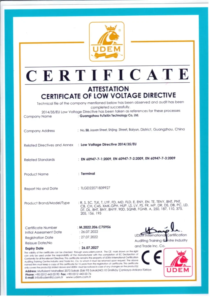
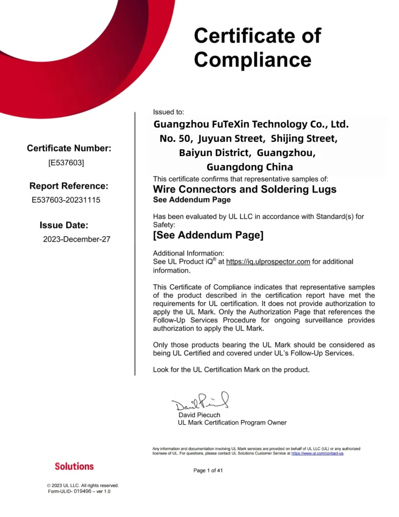
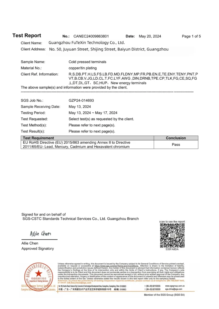
Certificate images: the CE attestation, the UL certification document and the SGS RoHS test report, shown as images only; numbers and dates are not shown here.