VOLTIXC / ENQUIRY
Request a Quote
Tell us what you need and we will review your enquiry.

By VoltixC Engineering Team · Last updated: 2026-09-28
Fast answer: To crimp a bullet connector, match the barrel to the wire gauge and the bullet diameter to its mating half, strip the wire to the barrel length, insert until the strands reach the end of the barrel, crimp with a tool sized for the insulation colour, then pull-test and push the male and female parts fully together.
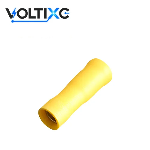
A bullet connector joins one wire to another with two crimp terminals: a round male pin on one lead and a hollow female receptacle on the other. Push them together and the circuit is made; pull them apart by hand and it opens again, with both crimps still on their wires. Each half carries two sizes. Its barrel has to suit the wire gauge, and its bullet has to suit the half it plugs into. VoltixC lists vinyl-insulated FRD female and MPD male bullet connectors in 22-16, 16-14 and 12-10 AWG bands.
Crimping is the joining method described here. Soldering is a different method, and none of the sources cited below describes it for bullet parts, so this page sticks to the crimp. Crimp tools appear by type only; VoltixC makes the connectors and sells no crimping tools.
Match the wire barrel to your wire gauge first, then the bullet diameter to the half it mates with, and last the insulation type, which sets how many crimps the barrel takes.
| Bullet check | What to match | Working value |
|---|---|---|
| Conductor fit | Your wire gauge against the band listed for the part | FRD and MPD parts cover 22-16, 16-14 and 12-10 AWG, or 0.5-1.5, 1.5-2.5 and 4-6 mm² |
| Gender | One male and one female half for each joint | MPD is the male pin and FRD the female receptacle; both halves come from the same band |
| Mating size | Bullet diameter of the male against the female | Not named on the FRD and MPD sheet, so it is confirmed per order; 3M lists bullet diameters of 0.156 in and 0.180 in for its bullet-style disconnects |
| Insulation and crimp count | Sleeve material against the crimp routine | Vinyl takes one crimp through the sleeve; many nylon-insulated terminals are designed for double crimping, which adds strain relief and tensile strength (Waytek) |
| Temperature rating | A stated rating, if the joint runs warm | 3M rates its vinyl-insulated bullet-style male disconnect for -40 to 105 °C; the FRD and MPD sheet prints 75 with no unit, so confirm a rating in writing before you specify one |
| Strip length | Bare conductor against the barrel | Wiltronics: strip enough insulation for the conductor to fill the terminal’s wire barrel without leaving unnecessary bare wire exposed behind the connector |
| Crimp tool | Die against the terminal and the wire | In TE Connectivity’s guide, a quality crimp requires correct tooling for the terminal and wire, the correct terminal for the application, properly prepared wire, and a trained operator |
| VoltixC item | Male code against female code | MPD1.25-156 with FRD1.25-156, MPD2-156 with FRD2-156, MPD2-195 with FRD2-195, MPD5.5-195 with FRD5.5-195 |
Source: FRD and MPD rows per supplier specification sheet, not individually re-tested; other rows from the sources cited below.
If a row stays blank, hold off on stripping. The FRD and MPD sheet names no bullet diameter, and halves bought from two sources may not mate, so get that number before the first cut.
| Also asked as | Short answer | Covered in |
|---|---|---|
| how to use bullet connectors | Crimp each half to its own wire, pull-test both, then push the male pin into the female receptacle until it seats | Step-by-step crimp |
| bullet connector sizes; bullet connector size chart | Two sizes on every half: the wire band and the bullet diameter. The FRD and MPD chart lists 22-16, 16-14 and 12-10 AWG with mm² and sleeve colour; the bullet diameter is confirmed per order | The two diameters |
| 16 AWG bullet connectors | 16 AWG sits on the edge of the 22-16 and 16-14 AWG bands; pick by the jacket outside diameter in mm and the die you crimp with | The two diameters |
| how to solder bullet connectors | Crimp or solder is a common forum question; this guide covers the crimp only, and none of its sources gives a solder method for bullet parts | Opening answer |
| crimper for bullet connectors | A crimper with a die nest for insulated terminals in the sleeve colour; VoltixC makes the connectors, not the tools | Step-by-step crimp |
| bullet connectors on solid wire | The steps assume stranded wire; for solid wire, check that the terminal maker lists solid conductors for that barrel | Step-by-step crimp |
| insulated vs bare bullet connectors | Insulated halves carry a sleeve to insulate the barrel; bare halves need a separate cover after the crimp | Types by insulation |
A bullet connector is a round male pin and a matching female receptacle, each crimped to its own wire, so the joint can be pushed together and pulled apart again by hand.
| Problem | What to do | Check |
|---|---|---|
| You need to tell the halves apart | Look for the pin; Del City describes a male bullet connector as a round pin that fits snugly into a hollow-bodied female bullet connector of the same size | A pin on one lead, a hollow receptacle on the other |
| The joint has to open for service | Fit a bullet pair. On its female bullet disconnect, 3M says dents and rolled edges provide holding force while allowing easy disconnection | The halves part with a firm pull by hand, and both crimps stay on their wires |
| You want to know what covers the male barrel | Check the maker’s description. On 3M’s male bullet snap plug, a funnel-shaped, rigid-molded PVC sleeve covers a butted-seam barrel | The sleeve comes out of the die whole, with no crack over the barrel |
| One lead stays live while the joint is open | Put the female half on that lead | The receptacle sits inside its sleeve to prevent a short; the bare pin is on the dead side |
| One end is a flat tab on a switch or relay | Use a blade quick disconnect | The mating part on the device is flat |
| The wire ends under a screw or on a stud | Use a spade or ring terminal from the crimp connectors range | The terminal sits under the screw head or nut |
| The joint never has to open | Use a crimped butt splice | No plug contact is left in the circuit |
| A new half has to mate with one already fitted | Match the band and the bullet diameter of the fitted half | The pin seats fully with hand force |
3M sells its male part as a snap plug, and other makers use other names for the same round pin. The FRD and MPD supplier sheet gives a brass body with tin plating under the PVC sleeve.
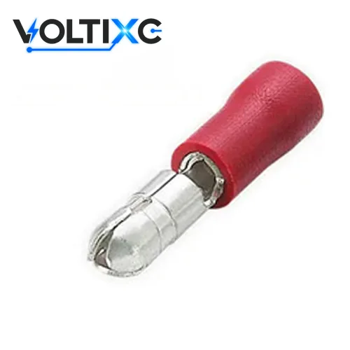
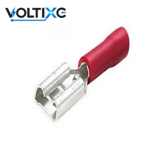
Choose a bullet connector for a slim wire-to-wire joint that unplugs by hand, and choose a blade quick disconnect when the other end is already a flat tab on a device.
| Feature | Bullet (round) | Blade quick disconnect | Which to choose when |
|---|---|---|---|
| Mating parts | Round male pin into a hollow female receptacle | Burndy describes a female quick disconnect as having a receptacle front end that slides onto and off a male blade | A tab already on the device calls for the blade |
| What it joins | Wire to wire | Wire to a tab on a switch, relay, heater or appliance terminal | The far end decides: another wire, or a device |
| Turning after mating | The round pin can turn inside the receptacle | The flat blade keeps one orientation | A lead that twists in service suits the round pin |
| Sizes to match | Wire band plus bullet diameter | Wire band plus tab width and thickness | Either way, two sizes go on the order |
| Space in the loom | Slim, in-line body | Wider, flat receptacle | Tight sleeves and bundles favour the bullet |
| Pull-apart force | Set by how the receptacle grips the pin | Set by how the receptacle grips the blade | This guide rates neither; ask the maker for the figure per part |
| VoltixC parts | FRD female and MPD male, vinyl | FDD female and MDD male vinyl parts, among others, on the FDD and MDD quick disconnect page | Order the family that matches the far end |
Source: joint types by product family (VoltixC supplier data as listed); the blade description comes from the Burndy document linked in the table.
Search for bullet vs spade connector and “spade” can mean two things: the flat blade in this table, or a fork terminal held under a screw. Blade sizes are set out in the guide to female spade connector sizes. A fork terminal on a screw strip belongs with the spade terminal range. A round pin will not seat in a flat receptacle, so the two systems cannot be mixed on one joint.
Bare and vinyl bullet connectors take one crimp, many nylon types are designed for two, and heat-shrink types get one crimp followed by heat on the sleeve.
| Insulation | Crimps | What the source says | On the VoltixC list |
|---|---|---|---|
| None (bare) | One on the barrel; any cover goes on afterwards | No insulation of its own | Not on the current list; ask before you specify |
| Vinyl (PVC) | One, through the sleeve | Waytek calls vinyl insulation the most economical option and says it gives basic protection against accidental contact | FRD female and MPD male, 22-16 to 12-10 AWG |
| Nylon | Two on many types: one on the wire barrel, one on the insulation | According to Waytek, many nylon-insulated terminals are designed for double crimping, which adds strain relief and tensile strength | Not on the current list; ask before you specify |
| Nylon, brass-sleeve | Per the maker’s instructions for that part | Del City lists nylon-insulated bullet connectors in standard designs and brass-sleeve versions, with full or partial insulation | Not on the current list; ask before you specify |
| Heat-shrink | One crimp, then heat on the sleeve after the pull test | On Del City‘s listing, heat-shrink insulated bullet connectors provide a watertight seal against corrosion and water damage | Not on the current list; ask before you specify |
| Point | What the data says | Source |
|---|---|---|
| Insulation range from one maker | Bullet-style connectors offered as male and female versions with vinyl, nylon, nylon-grip or heat-shrink insulation | Burndy product page |
| Body metal | Brass with corrosion-resistant tin plating on 3M’s bullet-style disconnects | 3M product page |
| Temperature rating | -40 to 105 °C for 3M’s vinyl-insulated bullet-style male disconnect | 3M product page |
| Sleeve colour | Insulated terminals use colour-coded insulators according to DIN cable sizes | ABB’s Spec-Kon guide |
Source: the maker and distributor pages named in each row; none of them describes FRD or MPD parts.
Colour charts differ from maker to maker, so read the band printed on the part or its label. On the FRD and MPD sheet the sleeve is red for 22-16, blue for 16-14 and yellow for 12-10 AWG over a tin-plated brass body, and the temperature figure is 75 with no unit, so confirm a rating in writing before you specify one.

The wire barrel is sized by the wire, and the bullet is sized by the half it plugs into, so every bullet order carries two sizes that are checked separately.
| Input | Where to get it | What it decides |
|---|---|---|
| Wire gauge (AWG) | Printed on the wire jacket or given on the drawing | The FRD or MPD band: 22-16, 16-14 or 12-10 AWG |
| Insulation outside diameter | Calipers on the jacket. Insulation outside diameters vary among wires with the same AWG size, so the insulation barrel must accommodate the wire’s outside diameter and the crimp range must match it (TE Connectivity) | Whether the sleeve closes on the jacket |
| Bullet diameter | The maker’s data for the half already fitted, or that half sent as a sample | Which pin or receptacle will seat |
| Side | The lead that stays live when the joint is open | Female on the live lead, male on the other |
| Insulation type | Where the joint sits: dry panel, vehicle loom or damp area | Vinyl from the list, or another sleeve asked for |
| Wire range (AWG) | mm² | Male part | Female part | Sleeve colour | Bullet diameter |
|---|---|---|---|---|---|
| 22-16 | 0.5-1.5 | MPD1.25-156 | FRD1.25-156 | Red | Confirmed per order |
| 16-14 | 1.5-2.5 | MPD2-156 or MPD2-195 | FRD2-156 or FRD2-195 | Blue | Confirmed per order |
| 12-10 | 4-6 | MPD5.5-195 | FRD5.5-195 | Yellow | Confirmed per order |
Source: part numbers, bands, mm² and sleeve colours per supplier specification sheet, not individually re-tested; 8 part numbers in the full specification table, request the complete sheet with your quote; bullet diameter confirmed per order.

Spec note: Del City lists the bullet connectors it sells from 0.156 in to 0.180 in in size. Those figures cover one seller’s range, so measure or look up the half already fitted before ordering its partner.
Take a 14 AWG lamp lead that has to plug into a harness already carrying a female bullet. Its gauge puts the new part in the 16-14 AWG band, so the male half is an MPD2-156 or MPD2-195. The second size comes from the fitted receptacle: read its diameter from its maker, or send it as a sample, and the MPD2 pin is matched to it per order.
Each half gets its own crimp and its own pull test before the male pin goes into the female receptacle.
Each joint takes one MPD male and one FRD female from the same wire band.
For a 14 AWG lead, that is an MPD2 on one wire and an FRD2 on the other.
Strip each wire far enough for the conductor to fill the wire barrel.
Look for whole strands and no nick in the copper.
The stripped end goes into the barrel until the strands reach its far end.
A jacket that stops well short of the sleeve means the strip was too long, so trim it.
Crimp the barrel in the die nest marked for that sleeve colour on the tool maker’s chart, taking the tool through its full stroke.
You should see one indent on the barrel, and the vinyl sleeve comes out unbroken.
Each crimped wire then gets a steady in-line pull.
A crimp that moves is cut off and replaced with a new terminal, and heat-shrink types wait for their heat until this test passes.
Push the male pin into the female receptacle until it seats fully.
If the pin stops short, it has not seated; recheck the band and the diameter.
| Step | What the source says | Source |
|---|---|---|
| 2, strip: clean cut on stranded wire | Insulation must be removed to the proper length cleanly, without nicking or breaking wire strands; the manual illustrates acceptable and rejected strip examples | TE Connectivity crimping guide (PDF) |
| 2, strip: length | Strip enough insulation for the conductor to fill the terminal’s wire barrel without leaving unnecessary bare wire exposed behind the connector | Wiltronics knowledge base |
| 4, crimp: two barrels | The wire barrel provides the electrical and mechanical connection, while the insulation barrel provides strain relief and requires a more relaxed crimp without providing an electrical connection | TE Connectivity crimping guide |
| 4, crimp: crimper and terminal | A quality crimp requires correct tooling for the terminal and wire, the correct terminal for the application, properly prepared wire, and a trained operator | TE Connectivity |
| 5, pull test | A crimp that moves or pulls out in a steady in-line pull test should be cut off and redone with a new terminal, and crimped terminals should not be reused | Wiltronics |
| 5, heat-shrink types | Heat-shrinking a sleeve must not be used to conceal or compensate for a loose crimp | Wiltronics |
| Batches | Reliable crimped electrical contacts require strict process controls and continuous pull-force process verification | NASA technical report |
Your standard or the terminal maker sets the pull-force values; none are given here. The general crimp method for rings, spades and other families is in how to crimp wires.
Tip: Tug each half right after crimping it, before the two are joined. A weak crimp is easier to reach while the joint is still open.

A mismatched pair either sits loose, which lets the contact wear and heat up, or has to be forced, which damages both halves; the fix is a matched pair from one band and one bullet diameter.
| Problem | What to do | Check |
|---|---|---|
| The pin slides in with almost no grip | Replace the pair with halves of one bullet diameter. A study published by IEEE identifies fretting corrosion as a typical problem in low-force electrical contacts | The new pin needs a firm push to seat and a firm pull to part |
| The joint works on the bench and cuts out on a vibrating machine | Cut out both halves and fit a matched pair, or a crimped butt splice if the joint never opens. In a Tribology International study, fretting can accumulate wear debris and oxidation products into a localized insulating layer, rapidly increasing contact resistance and eventually producing an open circuit | A meter across the joint stays steady while you flex the lead |
| The pin needs pliers or a hammer to go in | Stop and compare the two diameters; forcing a pin into a smaller receptacle can deform both halves | The pin enters with hand force alone |
| The sleeve by the joint is soft, discoloured or melted | Cut the joint out and replace both halves, since a loose contact heats up under current | No discolouration once the new pair has run under load |
| The halves come from two wire bands | Crimp a new pair from the band that fits the wire | Both codes carry the same number, MPD2 with FRD2 for example |
| The halves come from two makers | Get the bullet diameter of each before mixing them | Both diameters match on paper and in a test fit |
| A loose crimp was covered with heat-shrink | Cut it out and crimp a new terminal; Wiltronics says heat-shrinking a sleeve must not be used to conceal or compensate for a loose crimp | The pull test passes before any heat goes on |
Insertion and extraction force figures come from the terminal maker; this guide lists none. A pair that fails any row is replaced, both halves together, and neither half is bent or pinched to tighten the fit.
Caution: Never force a pin into a receptacle that resists hand pressure. Stop, compare the two diameters and swap the half that does not match.

Use bullet connectors on wire-to-wire joints you open for service, such as a vehicle lamp lead, a boat fitting, a panel door harness or the lead of a replaceable fan. Del City lists automotive, motorcycle, marine, industrial and general electrical projects as places bullet connectors are used.
| Application | Why a plug-apart joint helps | What to check |
|---|---|---|
| Cars and motorcycles | A light, sensor or accessory upgrade comes off without cutting the harness | Vibration at the joint; see the mismatch section above |
| Boats | A fitting unplugs for service or winter storage | Water: the vinyl FRD and MPD parts list no seal |
| Industrial panels | A door, lid or removable panel lifts off with its wiring | Slack on both sides, so the plug does not hang on its cable |
| Fans, lamps, sensors and small pumps in HVAC units and appliances | A replacement unit plugs straight into the half left in the harness | Band and bullet diameter of that harness half |
| Bench rigs and prototypes | Each rewire is a pull and a push, with no cut and no new crimp | A label on each lead with its AWG band |
On an engine or compressor frame that shakes all day, use a crimped splice instead of a bullet. Where spray or washdown reaches the joint, a sealed route such as the heat-shrink butt connector range or solder-seal connectors fits better, since the vinyl FRD and MPD parts list no seal. The FRD and MPD sheet prints 75 with no unit for temperature, so keep them away from heaters and hot lamp bases unless you hold a rating for the exact part.
VoltixC lists eight bullet connector part numbers, four FRD vinyl female and four MPD vinyl male, on its bullet connector page; they cover 22-16, 16-14 and 12-10 AWG, with a -156 and a -195 version on each side of the 16-14 AWG band.
| What to send | Why it matters | Example |
|---|---|---|
| Code or wire gauge | It sets the band | MPD2-156 and FRD2-156, or simply “14 AWG” |
| A count for each side | Male and female halves are quoted as separate lines | One count for MPD2-156, another for FRD2-156 |
| Bullet diameter to match | The FRD and MPD sheet does not name it | Diameter of the half already fitted, or that half as a sample |
| Insulation | Vinyl is listed; other sleeves are asked for | Vinyl, or the sleeve you need |
| Sleeve colour and pack | The sheet gives red, blue or yellow by band and 1,000 pieces per box | Any other pack or label text, confirmed per order |
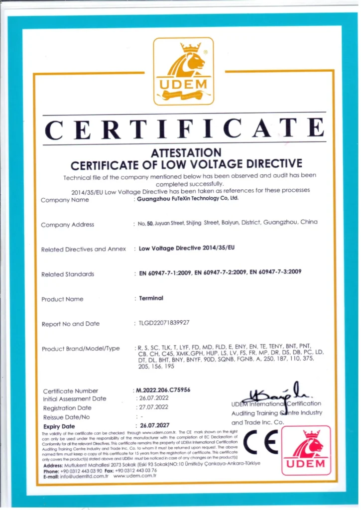
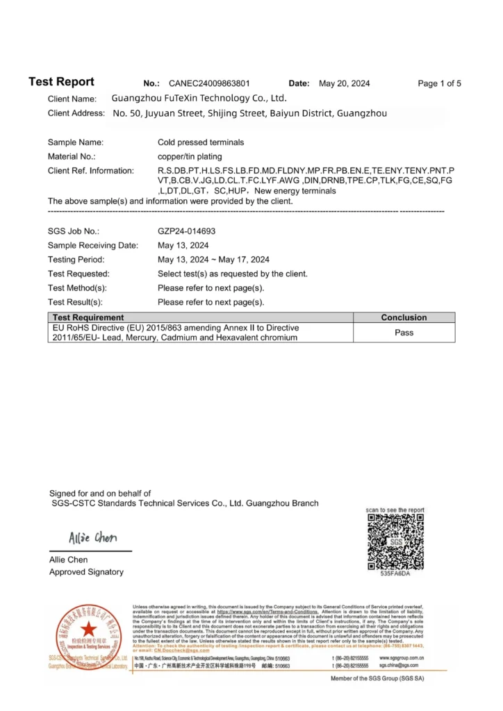
| Documents | CE under the Low Voltage Directive 2014/35/EU for the full terminal range, UL certified, RoHS test report available (SGS); numbers are not published here | The document you need on file for your order |
Drawings and photos of the fitted half go by email to hugo@voltixconnect.com, since the form takes no uploads. Quantities, samples and delivery are agreed per order in the reply. Rings, spades and splices sit beside the bullet in the guide to crimp connector types.
A plug-apart joint between two wires. One wire gets a round male pin and the other a hollow female receptacle of the same size; each is crimped on, then the two push together and pull apart by hand. On VoltixC’s list the pin is the MPD part and the receptacle is FRD, in three wire bands.
Round against flat. Burndy describes a female quick disconnect as having a receptacle front end that slides onto and off a male blade. A bullet pin won’t go into that receptacle. Look at the far end of your wire: another wire points to a bullet, and a tab on a relay or switch points to a blade.
The wire sets one and the mating half sets the other. A 14 AWG wire needs the 16-14 AWG barrel, so MPD2 or FRD2, while the pin has to fit whatever receptacle it meets. TE Connectivity also notes that insulation outside diameters vary among wires with the same AWG size. The FRD and MPD listings leave the pin size open, so it is confirmed per order.
Don’t try. Forcing bends both halves, and a pair that slides together with no grip leaves a loose, low-force contact that wears in service. Get the matching half in the right size; with FRD and MPD parts that means the same number on both codes, such as FRD2 with MPD2.
With nylon and heat-shrink sleeves. Waytek notes that many nylon-insulated terminals are designed for double crimping, which adds strain relief and tensile strength. Heat-shrink parts are heated once the pull test has passed. On a vinyl FRD or MPD part, one crimp through the sleeve closes the barrel.
Start with the wire gauge or the code and a separate count for the male and female side. If a half is already fitted in the harness, add its diameter or email a photo of it beside a ruler, because the enquiry form has no upload field. Sleeve colour and packing can go in the message box.
No, they differ on two counts. Barrels come in wire bands, 22-16, 16-14 and 12-10 AWG for FRD and MPD parts, and 3M lists bullet diameters of 0.156 in and 0.180 in for its bullet-style disconnects. Check the diameter before you mix brands in one harness.
How this guide was written: it follows one bullet joint from choosing the pair to mating it. The sources are TE Connectivity’s crimping guide, 3M and Burndy product pages, Del City, Waytek, Wiltronics, ABB’s Spec-Kon guide, two journal papers on fretting and a NASA technical report. VoltixC ran no tests for this guide and gives no pull-force or insertion-force figures. Part numbers, wire bands, mm² and sleeve colours come from the FRD and MPD supplier specification sheet and have not each been re-tested.
VoltixC is the brand of Guangzhou FuTeXin Technology Co., Ltd. It makes the FRD and MPD bullet connectors this guide uses as examples; crimp tools are outside its range.