VOLTIXC / ENQUIRY
Request a Quote
Tell us what you need and we will review your enquiry.

By VoltixC Engineering Team · Last updated: 2026-09-28
Fast answer: Cable lug dimensions on a drawing describe the barrel (inside diameter, outside diameter and length), the palm (width and thickness), the hole (diameter and distance to the end) and the overall length. Lugs for the same mm² differ by family, so confirm the angle, hole spacing and tolerances for your cabinet before you order.
A panel builder holds a supplier drawing next to a busbar that already has its holes drilled. The hole diameter and the distance from hole centre to palm end get checked first, since they decide whether the lug lands on the bar at all. Palm width goes against the slot in the enclosure after that, the barrel length against the room behind the door, and the barrel bore against the stranded conductor. The VoltixC range of cable lugs covers tube, DIN 46235, two-hole, narrow-palm and sight-hole families.
Family differences and fit checks here draw on DIN 46235 and DIN 46234 pages from Klauke, Weidmüller, LAPP and Phoenix Contact, plus the IEC 61238-1-1, EN 13600 and ASTM B258 scope summaries. Size-by-size values sit in the cable lug size chart. The letters follow the VoltixC specification sheets, where tube-lug rows print the barrel ID d, barrel OD D, overall length L, palm width B and stud hole Φ; palm thickness and tolerances are not printed and are confirmed per order against your drawing.
A cable lug drawing carries three groups of numbers, for the barrel, for the palm and hole, and for position and overall size, plus extra fields when the lug is angled, drilled twice or plated to a spec.
| Spec | What to capture | Working value |
|---|---|---|
| Barrel | d inside diameter, D outside diameter, barrel length (E or B, by sheet) | d and D printed for every VoltixC tube-lug part number; barrel length on most |
| Palm and hole | B palm width (W on some sheets), palm thickness, Φ stud hole diameter | According to Klauke, compression cable lug conductor nominal cross-sections range from 6 mm² to 1000 mm² and connecting-bolt holes from M5 to M20 |
| Position and overall size | Hole centre to palm end, L overall length | L printed for straight parts; hole centre to palm end is not printed and is confirmed per order |
| Special geometry | Angle, hole spacing, second barrel | VoltixC tube lugs are listed straight, at 45° and at 90°, and its 66 two-hole part numbers (AD and CL-2H) print the hole spacing |
| Sheet-metal terminal range | Conductor size and bolt hole on a DIN 46234 part | Klauke gives DIN solderless terminal conductor nominal cross-sections from 0.5 mm² to 240 mm² and bolt holes from M2 to M16 |
| Material and plating (per drawing) | Base metal, plating, temperature limit | LAPP lists electrolytic copper with a temperature range up to +120°C for its KB lugs |
| Second maker’s material line | Same fields on another data sheet | On Phoenix Contact’s ring lug, the material is copper with a tin-plated coating and the operating ambient temperature is 110°C |
| Tolerance line (per drawing) | Permitted deviation for each lettered value | Not printed on the VoltixC sheets; taken from your drawing and confirmed per order |
| Conductor size (mm² / AWG) | Cross-section and conductor class | mm² printed for every VoltixC tube-lug part, AWG or kcmil on most; conductor class confirmed per order |
| Type-test size span | Conductor areas a type-test standard covers | IEC 61238-1-1 specifies IEC 60228 conductor areas of 2.5–1200 mm² for copper and 16–1200 mm² for aluminium |
| Worked example at 300 mm² | Printed fields of one part number | DIN300-12 on the VoltixC DIN sheet: stud hole Φ 13, barrel ID d 24.5, barrel OD D 32, overall length L 119 and palm width W 46 mm |
Source: VoltixC rows per supplier specification sheet, not re-tested; other rows from the sources cited below.
Both 300 mm² and 630 mm² sit inside the 6–1000 mm² span Klauke gives for DIN 46235 compression lugs. On the VoltixC sheets, 300 mm² parts appear in eight series and 630 mm² parts in three, and the family comparison below lists their printed sizes.
| Also asked as | Short answer | Covered in |
|---|---|---|
| 300mm cable lug dimensions | Eight VoltixC series list 300 mm² parts; barrel ID runs from 23.4 to 26 mm and overall length from 87 to 133 mm | The 300 and 630 mm² table in the DIN 46235 family comparison |
| 630 sq mm cable lug dimensions | T630, LYF630 and SC630 are listed; barrel ID 34.5–39 mm and barrel OD 44.7–53 mm | The same table |
| copper cable lug dimensions | d, D, L, B and Φ on each tube-lug row; palm thickness and tolerance are confirmed per order | Which dimensions appear on every cable lug drawing |
| lug selection by drawing | Pick the family, then match d to the conductor, Φ to the stud and B to the slot | Which dimension checks predict a bad install |
| manufacturer lug drawing | Ask the manufacturer for the sheet row and add your tolerance line | How do you get VoltixC lug drawings |
Every cable lug drawing gives the barrel inside diameter, outside diameter and length, the palm width and thickness, the hole diameter, the hole centre-to-end distance, the overall length and the angle.
| Problem | What to do | Check |
|---|---|---|
| The conductor has to enter the barrel | Read d, the barrel inside diameter, against the stranded conductor | The stripped conductor goes in to the end of the bore without trimming strands |
| The die has to close on the barrel | Read D, the barrel outside diameter, against the die you plan to use | The die marking and D refer to the same lug size |
| Strip length depends on the barrel | Read the barrel length, lettered E on some VoltixC sheets and B on others, before you set the strip length | No bare strands show between the barrel and the insulation |
| The palm has to sit flat on the busbar, terminal or grounding bar | Read B, the palm width (W on some sheets), against the face it lands on | The palm stays inside the face with no overhang |
| The bolt clamps through the palm | Read the palm thickness with its tolerance; the VoltixC tube-lug sheets do not print it | The bolt length covers the palm, the bar and the washer stack |
| The bolt has to pass the hole | Read Φ, the stud hole diameter, against the stud or bolt size | The bolt goes through without reaming |
| The hole has to line up with the bar | Read the distance from hole centre to palm end on your drawing | The palm end clears the next conductor or wall |
| The lug has to fit the space | Read L, the overall length, plus the room the cable needs to bend | The door or cover closes with the cable seated |
| The cable has to leave the termination in one direction | Read the angle, 0°, 45° or 90°, and the side the palm turns to | The quote names both the angle and its direction |
| The drawing cites a standard | Check the standard named on the drawing; according to Klauke, DIN 46235 defines the applications, dimensions and designation of compression cable lugs | The standard number appears in the title block |
The letters follow the VoltixC tube-lug sheets: d, D, L, B and Φ. Check the legend on each sheet before you compare two drawings, because the same letter can mark a different feature, and B is the palm width on the T sheet but the barrel length on the DIN sheet. The compression and mechanical lug sheets letter their drawings A to H in their own way. Choosing a family comes before reading its drawing, and how to choose cable lugs covers that choice.
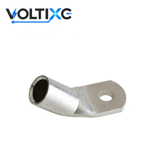
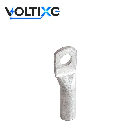
At one mm², a DIN 46235 compression lug, a tubular lug made from copper tube and a DIN 46234 solderless terminal are built from different stock to different documents, so their barrels and palms differ.
On a switchboard drawing that names DIN 46235, the standard fixes the lug geometry; a drawing that gives only a cross-section leaves the family open, and the barrel and palm then follow whichever maker’s table the quote uses.
| Family | What the standard or maker covers | Stock and finish | Conductors | Sizes and use | VoltixC page |
|---|---|---|---|---|---|
| DIN 46235 compression lug | DIN Media lists DIN 46235 as cable lugs for compression connections, cover plate type, for copper conductors | Tube; Klauke’s DIN lugs are made from electrolyte copper and tin plated as standard for corrosion protection | Round conductors of EN 60228 classes 1, 2, 5 and 6 on Klauke’s DIN lugs | 6 mm² to 1000 mm², bolt holes M5 to M20 (Klauke) | DIN 46235 cable lugs, 68 part numbers in 18 cross-sections |
| Tubular lug from drawn copper tube | EN 13600 specifies composition, property requirements including electrical properties, and dimensional and form tolerances for seamless drawn copper tubes used for electrical purposes (iTeh summary) | Tube; the tube standard is industry context and is not stated for VoltixC parts | Set by each maker’s table | Set by each maker’s table | tinned copper lugs: T, TL, TLK, LYF and CL-H series |
| DIN 46234 solderless terminal | According to Klauke, DIN 46234 solderless terminals have standard requirements for application, dimensions and designation | Made from copper sheets, unlike compression lugs made using tubes, with a soldered joint (Klauke) | Round conductors of EN 60228 classes 2, 5 and 6 on Klauke’s terminals | Klauke names control cabinet construction and rail-vehicle construction as uses | Not on the current list; ask before you specify |
Source: DIN Media, iTeh Standards and Klauke pages listed under References; none of them describes VoltixC parts.
| Point | What the data says | Source |
|---|---|---|
| DIN 46235 conductor builds | DIN 46235 compression cable lugs may be used for one, several, fine and super-fine stranded conductors | Klauke |
| DIN 46235 cable types | The lugs are for non-tension copper cables such as DIN 48201-1 and pre-rounded multi-stranded sector conductors | Klauke |
| DIN 46234 conductor builds | DIN 46234 solderless terminals are crimped with several, fine and super-fine stranded conductors | Klauke |
| Both families in one range | The accessory range lists compression cable lugs to DIN 46235 and sheet-metal cable lugs to DIN 46234 | Weidmüller |
| A sheet-lug catalogue | KB products are uninsulated cable lugs/solderless terminals according to DIN 46234 made from electrolytic copper | LAPP |
| Where sheet lugs go | The application range includes cables with category 2, 5 and 6 conductors, control cabinets/equipment, and trains/buses | LAPP |
| One maker’s build | The ring cable lug is designed according to DIN 46234, brazed and tin plated | Phoenix Contact |
Source: maker pages named in each row.
On the VoltixC sheets, a 300 mm² lug has a barrel ID from 23.4 to 26 mm and an overall length from 87 to 133 mm, depending on the series.
| Part number | mm² | Stud holes listed (mm) | Barrel ID (mm) | Barrel OD (mm) | Overall length (mm) | Palm width (mm) |
|---|---|---|---|---|---|---|
| DIN300 (4 part numbers) | 300 | 13, 15, 17, 21 | 24.5 | 32 | 119–122 | 46 |
| T300 (5 part numbers) | 300 | 10.5, 13.2, 14.5, 16.5, 21 | 23.4 | 28.6 | 96 | 42 |
| TL300 (4 part numbers) | 300 | 10.5, 13, 14.5, 16.5 | 23.4 | 28.6 | 133 | 41.7 |
| LYF300 (5 part numbers) | 300 | 10.5, 13, 17, 21, 26 | 26 | 32 | 114 | 47 |
| TLK300 (4 part numbers) | 300 | 13, 15, 17, 21 | 23.5 | 29.5 | 111 | 43 |
| SC300 (5 part numbers) | 300 | 10.5, 13, 15, 17, 21 | 24 | 30 | 100 | 43.7 |
| DT300 (2 part numbers) | 300 | 17, 21 | 24 | 31 | 120 | 45 |
| XK300 (3 part numbers) | 300 | 10.5, 13, 17 | 23.5 | 31.3 | 87 | 31 |
| T630 (5 part numbers) | 630 | 10.5, 13.2, 14.5, 16.5, 21 | 34.5 | 44.7 | 133.1 | 64 |
| LYF630 (2 part numbers) | 630 | 21, 26 | 39 | 53 | 180 | 75 |
| SC630 (5 part numbers) | 630 | 10.5, 13, 15, 17, 21 | 35 | 45 | 135 | 65 |
Source: VoltixC supplier specification sheets, one row per series and size; palm width is lettered B on some sheets and W on others; values not re-tested.
A drawing with no standard on it needs the family written on the enquiry. Send the conductor class and the busbar or bolt size with it, and the quote names the family and its table. Check that the die marking matches the lug family before a sample crimp.
Tip: When a drawing gives only mm², ask which family it means before you compare lettered values; a tube lug and a sheet terminal of the same mm² are different parts.
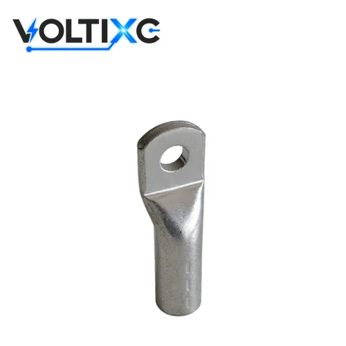
A two-hole palm adds the hole spacing, an angled palm adds the angle and its direction, a flared entry adds the mouth diameter, a sight hole adds its position, and a double barrel adds the barrel spacing.
On a crowded busbar with pre-drilled holes, the spacing between two bolt holes decides the lug before its wire band does. In a shallow enclosure the cable exit angle comes first.
| Construction | Extra dimension you must specify | Why it matters | VoltixC series |
|---|---|---|---|
| Two-hole palm | Centre-to-centre spacing of the two holes and the diameter of each | Both holes have to meet holes already drilled in the bar | AD and CL-2H on the two-hole lugs page, 66 part numbers with the hole spacing printed for each |
| 45° or 90° palm | The angle and the side the palm turns to | It sets where the cable leaves the terminal | T and LYF listed straight and at 45°, TLK straight and at 90°; the copper compression lugs are listed at 0°, 45° and 90° |
| Sight hole in the barrel | Distance of the hole from the barrel end | The installer sees the conductor tip before crimping | GC series on the copper tube ring terminals page; position confirmed per order |
| Flared (bell-mouth) entry | Mouth diameter and flare length | Strands are guided into the bore | GC series, which pairs the sight hole with a bell mouth |
| Narrow palm or narrow tongue | Palm width at the hole and at the barrel | The palm has to pass a slot on a breaker or terminal block | TPE and XK on the narrow-palm copper lugs page |
| Double barrel | Spacing between barrels and the bore of each | Two conductors land on one palm | Not on the current list for compression lugs; custom tooling on request, so ask before you specify |
| Blank palm for drilling on site | Palm size with no hole, or the hole size to be drilled | The hole is set by the installer | Not on the current list; custom tooling on request, so ask before you specify |
Source: construction descriptions are general; VoltixC series, angles and hole spacing per supplier specification sheet.
A construction missing from the table is a special request. Send a sketch with the extra dimension marked, and the quote states whether tooling is needed.
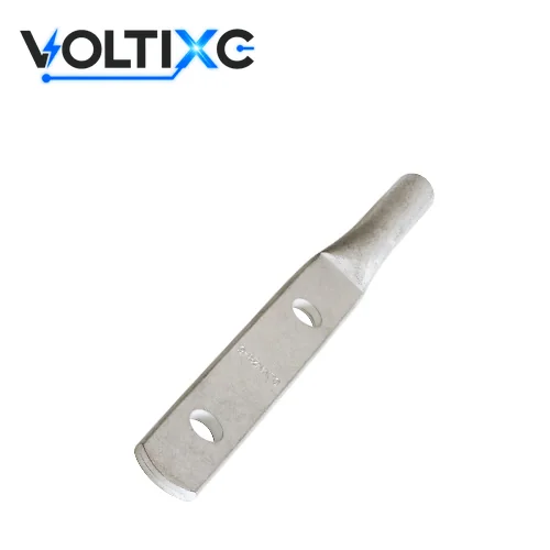
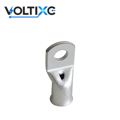
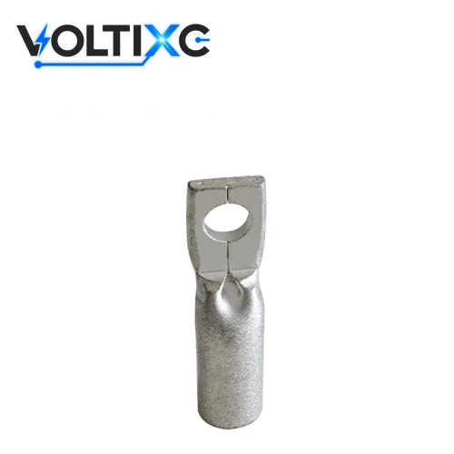
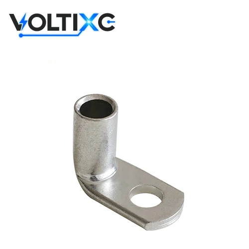
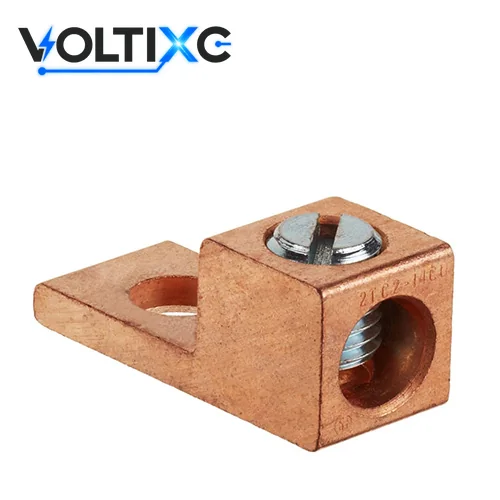
A mechanical lug adds the set-screw size and its tool, the wire range of each barrel, the barrel count and the mounting-hole spacing; a bimetallic lug adds the joint between an aluminium barrel and a copper palm.
The conductor in a mechanical lug sits under a screw instead of a crimp, so its drawing describes the clamp as well as the palm.
| Field | What to read on the drawing | Why it matters | VoltixC |
|---|---|---|---|
| Set screw | Thread size and the key or driver it takes | The installer brings the right tool and the maker’s tightening instruction | Hex size or slot printed per catalogue number; tightening torque is not listed and comes per model with the quote |
| Wire range per barrel | Smallest and largest conductor each barrel accepts | One barrel may take a range, not a single size | Printed per catalogue number, from #14 AWG to 1000 kcmil |
| Barrel count and stacking | One barrel, two side by side, or stacked | Each extra barrel adds a conductor and a spacing figure | On the aluminum and copper mechanical lugs page, AM bodies take up to four conductors and CM stops at one conductor or two holes |
| Mounting holes | Number of holes, their diameter and spacing | The base bolts to a panel or bar with those holes | Bolt size printed per catalogue number; hole count and spacing confirmed per order |
| Anti-turn rib | Whether the base has a rib that keys into the panel | A rib stops the lug from turning as the screw is tightened | Confirmed per order |
| Conductor rating | Copper only, or aluminium and copper | The body material limits which conductor goes in | AM bodies are aluminum; CM bodies are listed as aluminum alloy and named for copper conductors; conductor rating is not stated on the sheets |
| Bimetallic joint | Position of the joint between aluminium barrel and copper palm | The copper face goes on the copper bar, the aluminium barrel on the conductor | Not on the current list; ask before you specify |
Source: field descriptions are general; VoltixC entries per supplier specification sheet and series summary.
The bimetallic row is an industry note. VoltixC lists aluminium and copper mechanical lugs, and the aluminium one-hole and two-hole compression lugs, but no copper-aluminium bimetallic part.
Match each column to its letter on the sketch, read the tolerance line under the table, and take plating thickness from the drawing notes.
A row in a lug table is one part: its conductor size, then the lettered sizes in millimetres, then angle, plating and tolerance. On the VoltixC tube-lug sheets each row prints mm² with d, D, B and Φ, and straight lugs add L; all are tin-plated copper. The template below marks what the sheet prints and what the quote confirms. Convert AWG to mm² from the wire standard, and leave the lug code out of that step.
| Column | What it holds | On the VoltixC sheet |
|---|---|---|
| Item | The maker’s part code for the lug or connector | Part number as printed, such as DIN300-12 or TLK50-10-90D |
| mm² / AWG | Conductor cross-section or gauge | mm² on every tube-lug row; AWG or kcmil on most |
| Barrel ID (d) | Bore the conductor enters | Printed |
| Barrel OD (D) | Outside of the barrel the die closes on | Printed |
| Barrel length (E or B) | Length available for the crimp | Printed on most rows; the letter differs by sheet |
| Palm width (B or W) | Width of the flat contact face | Printed |
| Palm thickness | Thickness under the bolt | Not printed; confirmed per order |
| Stud hole (Φ) | Bolt or stud clearance | Printed |
| Hole centre to end | Distance from hole centre to palm tip | Not printed; confirmed per order |
| Overall length (L) | Tip of the palm to the barrel end | Printed for straight parts; angled parts give leg lengths |
| Angle | 0°, 45° or 90° | Listed for T, LYF, TLK and the copper one-hole and two-hole compression lugs |
| Plating thickness | Coating on the copper | Plating listed as tin; thickness confirmed per order |
| Tolerance | Permitted deviation per dimension | Not printed; taken from your drawing and confirmed per order |
Source: VoltixC entries per supplier specification sheets for the tube-lug series; not re-tested.
| Point | What the data says | Source |
|---|---|---|
| AWG sizes | ASTM B258 prescribes standard nominal diameters and cross-sectional areas for AWG sizes of solid round wires used as electrical conductors | ASTM |
| AWG calculations | ASTM B258 gives equations and rules for calculating nominal mass, lengths, resistances, and breaking or rated strengths of AWG wires | ASTM |
| Tool code on the lug | A code number provides clear tool assignment for the DIN cable lugs | Klauke |
| Tube material line | The cable lugs are copper under EN 13600 and tin plated to protect against corrosion | Klauke |
| Sheet material line | The material is copper under EN 13599 and the surface is tin plated for corrosion protection | Klauke, solderless terminals |
| Temperature on one data sheet | The material is electrolytic copper and the temperature range is up to +120°C | LAPP |
| Temperature on another | The material is copper with a tin-plated coating and operating ambient temperature is 110°C | Phoenix Contact |
Source: ASTM, Klauke, LAPP and Phoenix Contact pages listed under References; the temperature figures belong to those makers’ parts.
Spec note: Write d, D, L, B and Φ in millimetres with the tolerance beside each value; plating thickness goes in the notes, not in a lettered column.
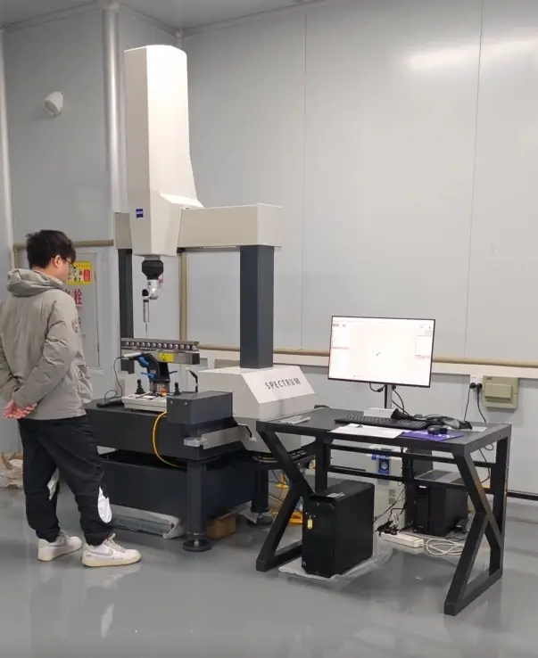
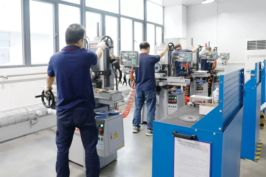
Check palm width against the terminal slot, barrel length against the enclosure depth, hole spacing against the busbar, the barrel and joint against the crimp, and the angle against the cable route.
| Problem | What to do | Check |
|---|---|---|
| The palm is wider than the slot on the breaker or terminal block | Compare B (W on some sheets), tolerance included, with the slot width on the device drawing | The palm slides into the slot by hand at a trial fitting |
| The barrel and the cable bend need more depth than the enclosure has | Add L to the bending room the cable needs and compare the total with the depth | The cover closes after installation with the cable seated |
| Two-hole spacing differs from the busbar | Match the hole centres to the holes drilled in the bar, and name the spacing on the enquiry | Both bolts go in without forcing the palm |
| A sector conductor goes into a round barrel | According to Klauke, sector conductors should be pre-rounded with the corresponding tool before processing | The rounded conductor enters the bore d to full depth |
| The die shape does not suit the lug | Klauke reports that the standard recommends hexagonal crimping dies according to DIN 48083-4 for processing compression cable lugs | The die marking matches the lug size |
| The barrel wall splits under the die | Ask for the wall, half of D minus d, and the die the maker names as compatible with that lug | A sample crimp shows no split |
| A sheet terminal opens at its seam | Ask how the seam is joined; Klauke says soldered-joint quality is key to the crimping result and poor joints may open during crimping | The seam stays closed after a sample crimp |
| The crimp area of a sheet terminal is only folded | Ask which joining process the crimp area uses; Klauke’s DIN 46234 terminals use a brazing process there | The quote names the process |
| Pull-out strength is questioned | Ask how the press zone is made; Phoenix Contact describes its hard-soldered press zone as intended to achieve maximum conductor pull-out values | The reply names the press-zone build |
| An angled lug arrives turned the wrong way | Write 45° or 90° and the side the palm turns to | The cable leaves toward its route |
Klauke and Phoenix Contact describe their own parts in these rows. For a VoltixC order, the joint build and the die are confirmed per order, and a sample crimp on your conductor settles the barrel checks.
Caution: Do not file a palm narrower or drill a hole larger to make a lug fit. Order the part with the right B and Φ instead.
Dimensions tell you a lug fits; a type test on the crimped joint tells you it keeps carrying current under heat and fault load, and the result belongs to whoever ran the test.
| Problem | What to do | Check |
|---|---|---|
| The drawing fits, and you also need the joint tested | Ask which standard the maker tested to and for which sizes; IEC 61238-1-1 specifies IEC 60228 conductor areas of 2.5–1200 mm² for copper and 16–1200 mm² for aluminium | The report names the standard, the conductor and the lug size |
| A maker says its lugs are IEC tested | Read the size range the statement covers; Klauke lists its DIN cable lugs as covering 10–800 mm² with IEC testing | Your size sits inside that range |
| A report covers another die or conductor class | Ask whether the tested lug, die and conductor match your order | All three match, or the gap is written down |
| You want heat-cycle or short-circuit withstand figures | Read them from the report itself; this guide gives no test figures | Each figure has a report number behind it |
| You see test equipment in factory photos | Treat the photos as equipment on site, not as reliability data for your order | The checks for your order are named in the quote |
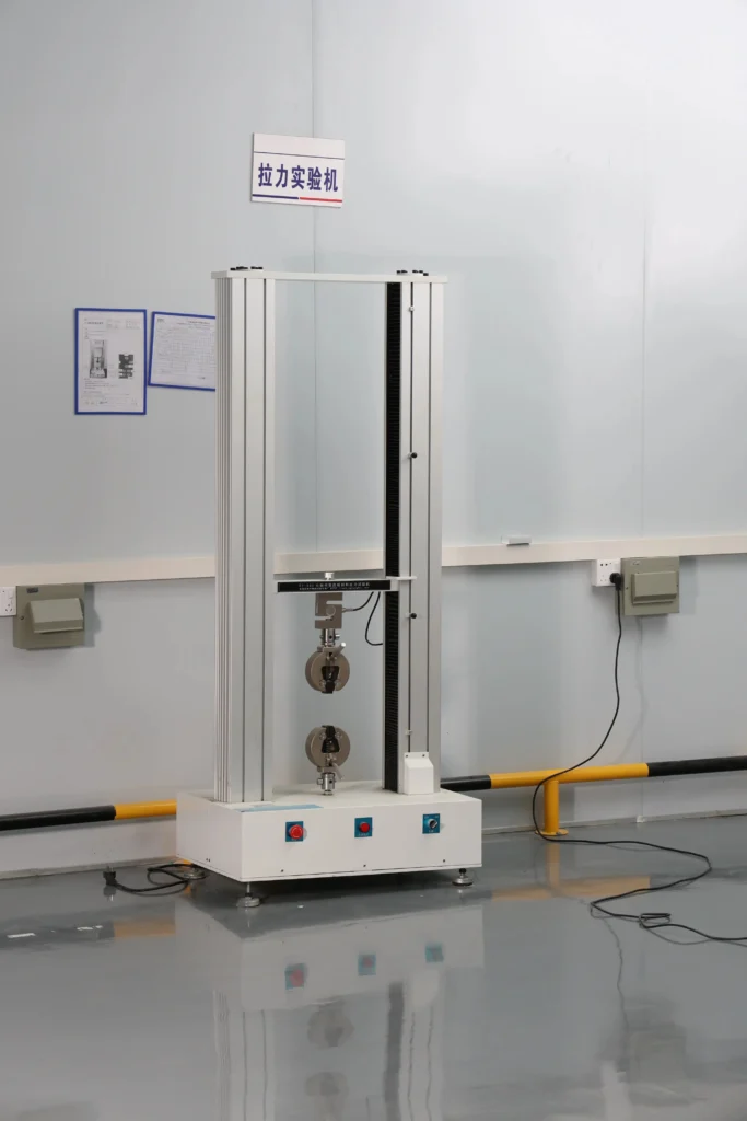
Naming IEC 61238-1-1 here is not a claim that VoltixC parts were tested to it. The temperature-rise tester, thermal shock chamber and tensile tester below are equipment photos; the checks run on an order are agreed with the quote.
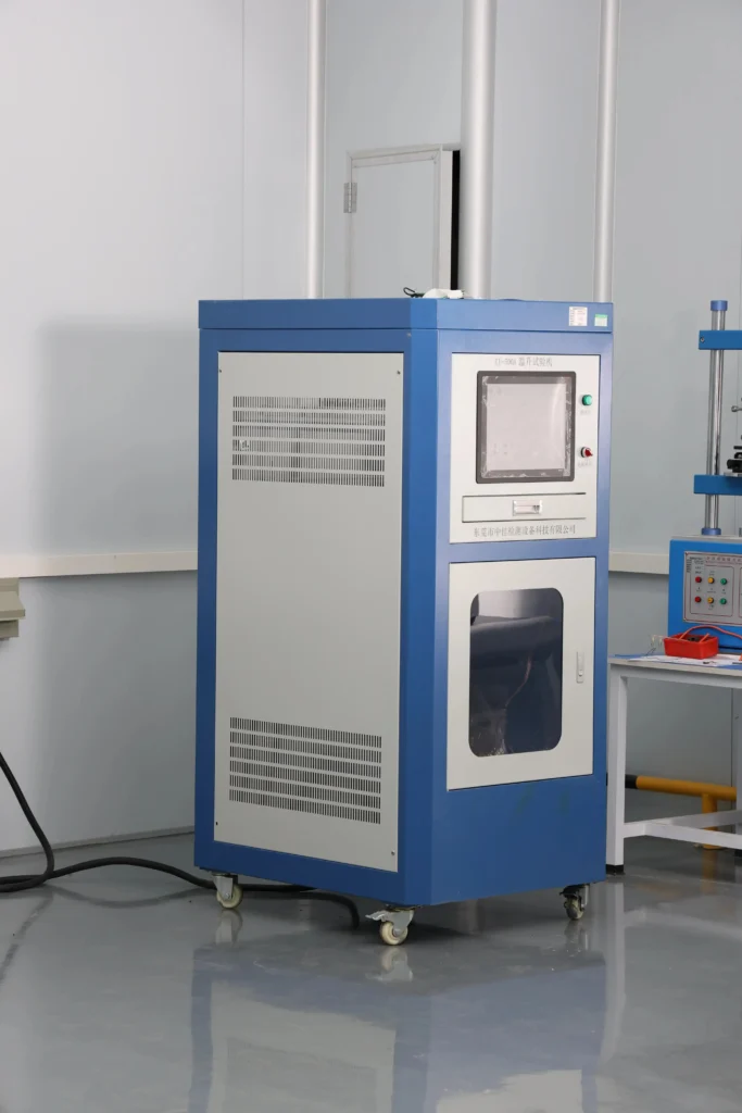
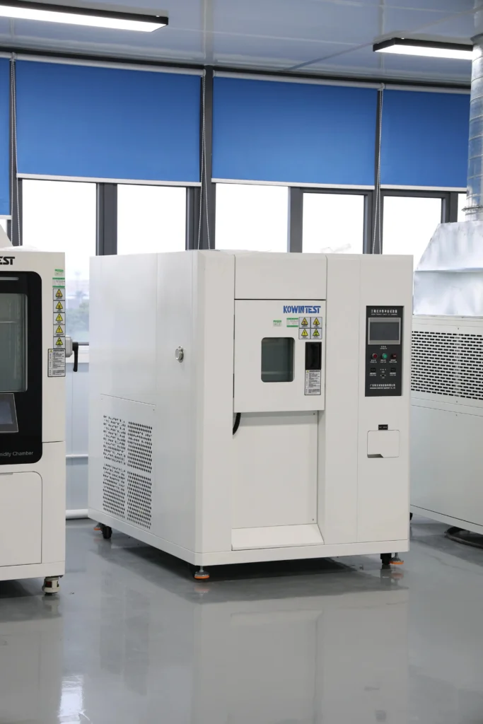
Send the conductor size, the bolt or stud size, the hole count and the angle with your enquiry; whether a dimension drawing comes with the quote is confirmed per order.
| What to send | How to write it | Letters it fixes |
|---|---|---|
| Conductor size and class | mm² or AWG, plus stranded, fine-stranded or sector | d, D and the barrel length |
| Bolt or stud size | Metric or inch bolt, one per hole | Φ |
| Hole count and spacing | One hole, or two holes with centre-to-centre spacing | Φ and the hole spacing |
| Angle and direction | 0°, 45° or 90°, and the side the palm turns to | Angle |
| Space limits | Slot width at the terminal, depth behind the cover | B, L |
| Plating and material | Bare or tin-plated copper, or the plating named on your drawing | Material line |
| Tolerances | The tolerance line from your drawing | All lettered values |
| Quantity per line | A count for each item | — |
Families you can quote from: tinned copper tube lugs, DIN copper compression lugs, two-hole copper lugs and the narrow-palm and narrow-tongue lugs. Wire-to-lug lookups sit in the copper lug size chart, and the background on the standard is in the DIN 46235 guide.
Drawings and photos can go by email to hugo@voltixconnect.com. Quotes state the sample timing, with fastest sampling from 7 days, confirmed per order. Quantities and delivery are agreed per order in the reply.
The inside diameter tells you whether the stranded conductor enters the barrel, and the outside diameter, with the wall between the two, is the copper the die squeezes. On DIN lugs Klauke ties each part to its crimp tool with a code number, so the die is chosen from the lug and not from the wire alone.
Palm width B (W on some sheets) sets how much of the bar or slot face the lug covers, and palm thickness adds to the stack under the bolt head, so both go against the busbar drawing before you order.
The spacing between the two hole centres, plus the diameter of each hole. Two-hole lugs have to meet a pair of holes already drilled in the bar, and a spacing that is off by the width of a bolt stops the second bolt going in. VoltixC lists 66 two-hole part numbers in the AD and CL-2H series, and the specification sheet prints the spacing for each.
A 45° or 90° palm sends the cable out in a different direction from a straight one, and the drawing has to say which way the palm turns. VoltixC lists its T and LYF tube lugs straight and at 45°, and TLK straight and at 90°.
No, because Klauke makes DIN 46234 solderless terminals from copper sheets with a soldered joint, unlike its compression lugs made using tubes, and the barrel and palm change with the stock.
It protects the fit. A palm width at the top of its tolerance may not enter a narrow slot, and a hole at the bottom of its tolerance may not pass the bolt. Put the tolerance line from your drawing on the enquiry, since the VoltixC specification sheets print no tolerance for any listed part.
A lug is specified by conductor size, material and plating, the lettered dimensions, the hole count, the angle and the temperature limit its maker states. Phoenix Contact, for one, gives copper with a tin-plated coating and an operating ambient temperature of 110°C for its ring lug, and that figure belongs to Phoenix Contact’s part.
How this guide was written: the letter meanings follow the VoltixC supplier specification sheets, and the fit checks follow common drawing practice and the DIN 46235 and DIN 46234 pages published by Klauke, Weidmüller, LAPP and Phoenix Contact. Standard scopes come from the DIN Media, iTeh Standards, ASTM and IEC Webstore listings. VoltixC ran no tests for this guide. The part numbers, angles and printed sizes come from those sheets and have not been re-tested; palm thickness, plating thickness and tolerances are not printed there and are confirmed per order.
VoltixC is the brand of Guangzhou FuTeXin Technology Co., Ltd. It makes the tube, DIN 46235, two-hole, narrow-palm and mechanical lug families this guide uses as examples; crimp tools are outside its range.